Yes, thats what the tables say but... parts like these have been made for a very long time on comparatively humble machines. Consider watchmakers have been making smaller holes using HSS tooling for a long time on rope driven spindles, maybe 20-25K? not remotely close to 60K. Now maybe they are special chisel type drills, thinner stock etc, but the point is its been done. Usually with drills its an excessive chip load issue & it doesnt take much infeed at all before it becomes problematic. I think the heyday of locomotive slike this was 60's & 70's before carbide was even on the map for mere mortals, so they obviously figured it out.I looked up a couple of rpm recommendations for #80 bit and brass,, 60,000ish rpm and a 118 degree grind. That's an insane speed

-
Scam Alert. Members are reminded to NOT send money to buy anything. Don't buy things remote and have it shipped - go get it yourself, pay in person, and take your equipment with you. Scammers have burned people on this forum. Urgency, secrecy, excuses, selling for friend, newish members, FUD, are RED FLAGS. A video conference call is not adequate assurance. Face to face interactions are required. Please report suspicions to the forum admins. Stay Safe - anyone can get scammed.
-
The 2026 Calgary Area Meetup is set for Saturday May 30th at 10am. The signup thread is here! Robinhood has graciously offered to host the meetup again this year. Please note that you MUST RSVP to the notice linked above if you wish to come.
You are using an out of date browser. It may not display this or other websites correctly.
You should upgrade or use an alternative browser.
You should upgrade or use an alternative browser.
New Projects New Challenges
- Thread starter carrdo
- Start date
HI Peter,
It will be the in and out finger control spring loaded micrometer sensitive feed model. It is not here yet. I think the HSS drill being a little more flexible than carbide will be better if there is any small misalignment. The #80 HSS drill which snapped off didn't seem to be bothered by that. I will try the carbide drills you showed if I get another failure. The blower ring jet is a high pressure steam jet taking pressure directly from the locomotive boiler so a little bit of misalignment is not critical.
It will be the in and out finger control spring loaded micrometer sensitive feed model. It is not here yet. I think the HSS drill being a little more flexible than carbide will be better if there is any small misalignment. The #80 HSS drill which snapped off didn't seem to be bothered by that. I will try the carbide drills you showed if I get another failure. The blower ring jet is a high pressure steam jet taking pressure directly from the locomotive boiler so a little bit of misalignment is not critical.

Hi All,
While waiting for all of the bits and pieces to arrive for round two on drilling the #80 drill holes in the steam jets, I decided to tackle the last major workshop build that I probably will ever do and that is to construct the very advanced miniature tube and pipe bender which was described by a retired Rolls Royce tooling engineer from memory of the ones used there to bend all of the stainless and other exotic tubing used in aircraft engine production.
The two part construction series was described in Model Engineer's Workshop magazine No. 94 dated November 2003. It was awarded the silver medal and the Bowyer-Lowe Challenge cup at the 72nd Model Engineer Exhibition.
It is not a beginners project and to be really useful, it has many accessories which need to be built (much like the Quorn) to handle every and any type of simple or complicated bending job that may ever come up. And it is not easy to build. I found this out right from the start.
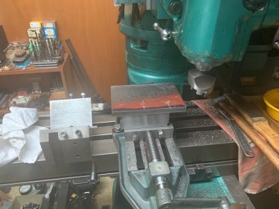
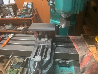
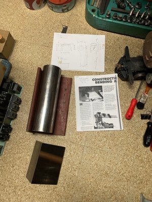
To start with it requires a length of 6" x 4" structural steel angle 1/2" thick and a 12" long piece of 3-1/4" diameter round mild steel bar as seen in photo 4. You don't just go into your local metal supplier and say you want what you see in the photo because structural angle that heavy is not all that common and if they do manage to find any, the price will bankrupt you.
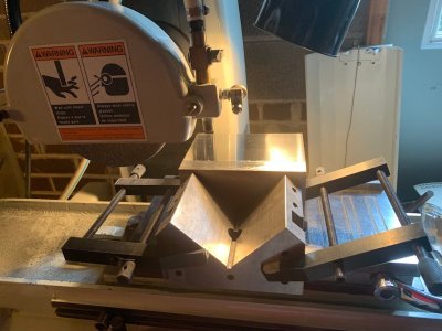
Anyway, the first preliminary operation after roughly cutting the pieces to length is to square the angle on all sides and on its outer faces. This alone took hours and hours. And since I finished only one of the pieces on the hand traverse surface grinder (the setup as seen was at the capacity limit of the machine), many additional hand cranking hours were involved to do this. I do not want to do this ever again.
To face and put centres in the bending head, the 3-1/4" diameter round bar has to be set up in a fixed steady. My 13" SB fixed steady will just do it as it is right at its absolute maximum capacity. And that bar weighs 30 lbs. Nothing for a commercial shop but something else for my home shop machines.
to be continued.
While waiting for all of the bits and pieces to arrive for round two on drilling the #80 drill holes in the steam jets, I decided to tackle the last major workshop build that I probably will ever do and that is to construct the very advanced miniature tube and pipe bender which was described by a retired Rolls Royce tooling engineer from memory of the ones used there to bend all of the stainless and other exotic tubing used in aircraft engine production.
The two part construction series was described in Model Engineer's Workshop magazine No. 94 dated November 2003. It was awarded the silver medal and the Bowyer-Lowe Challenge cup at the 72nd Model Engineer Exhibition.
It is not a beginners project and to be really useful, it has many accessories which need to be built (much like the Quorn) to handle every and any type of simple or complicated bending job that may ever come up. And it is not easy to build. I found this out right from the start.
To start with it requires a length of 6" x 4" structural steel angle 1/2" thick and a 12" long piece of 3-1/4" diameter round mild steel bar as seen in photo 4. You don't just go into your local metal supplier and say you want what you see in the photo because structural angle that heavy is not all that common and if they do manage to find any, the price will bankrupt you.
Anyway, the first preliminary operation after roughly cutting the pieces to length is to square the angle on all sides and on its outer faces. This alone took hours and hours. And since I finished only one of the pieces on the hand traverse surface grinder (the setup as seen was at the capacity limit of the machine), many additional hand cranking hours were involved to do this. I do not want to do this ever again.
To face and put centres in the bending head, the 3-1/4" diameter round bar has to be set up in a fixed steady. My 13" SB fixed steady will just do it as it is right at its absolute maximum capacity. And that bar weighs 30 lbs. Nothing for a commercial shop but something else for my home shop machines.
to be continued.
Attachments
Looking forward. Strangely I cant find a single picture, can you provide a sneak peak or describe what makes it special (and relatively heavy)?very advanced miniature tube and pipe bender
I've collected a few designs through various model engineering & fabrication sources. Some features I like, some I don't, so modeled something in between. But its on the to-do list until tubing time comes along.
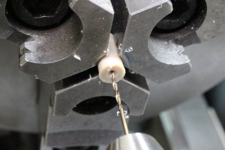
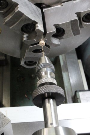
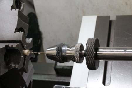
Oh and (unrelated) a few pictures for you. I used my sensitive drill Albrecht in the tailstock the other day in some grabby GF30 PEEK 0.8 and 1.0mm dia hole x 20mm long in peck mode. It worked pretty good. You absolutely need a proper spot drill >= drill included angle on the small stuff. As mentioned before I've drilled smaller diameter holes than this with carbide circuit board drills which have a nominal larger shank, 3 or 4mm I cant recall. I actually prefer them, I can grip them in a conventional precision chuck. But you have no infeed feel with the tailstock wheel & pecking is clunky. The Albrecht wins on that front. I bought mine used in excellent shape from someone on the forum a while back, but I'd have hard time coughing up dough for a new one.
Attachments
Hi Peter,
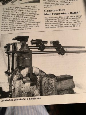
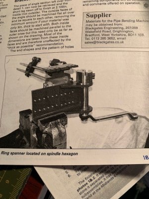
Here are a couple of shots of the overall bender from the construction articles (Nov. 2003, Dec.-Jan. 2004 MEW). I can't send the actual construction drawings from the articles as they are marked copyright. But there are many sources for back issues of Model Engineers Workshop if the project looks to you worth undertaking.The tooling though is really something.
Here are a couple of shots of the overall bender from the construction articles (Nov. 2003, Dec.-Jan. 2004 MEW). I can't send the actual construction drawings from the articles as they are marked copyright. But there are many sources for back issues of Model Engineers Workshop if the project looks to you worth undertaking.The tooling though is really something.
Attachments
Hi All,
The battle continues.
I now have everything necessary to have a second go at this.
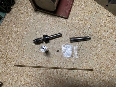
The special, ultra sensitive miniature hand feed Albrecht drill chuck, with micrometer feed, like Peter T, I bought used but it was like new. It was just dirty and needed a thorough cleaning and oiling to operate smoothly. These chucks do not come up often so when they do and if you need one...
It was expensive enough but not anything like the new price. It will be held in a 1/2" ID MT 2 collet in the tailstock of the 9" SB lathe. You do not use the tailstock hand wheel for this drilling operation.
I am now holding the 3/16" brass hex bar stock in a purpose 3/16" 3C hex collet to minimize runout instead of a 3 jaw chuck as in the first go round. Also, I now have a dozen #80 HSS drills to play with. We will see how it all goes.
The battle continues.
I now have everything necessary to have a second go at this.
The special, ultra sensitive miniature hand feed Albrecht drill chuck, with micrometer feed, like Peter T, I bought used but it was like new. It was just dirty and needed a thorough cleaning and oiling to operate smoothly. These chucks do not come up often so when they do and if you need one...
It was expensive enough but not anything like the new price. It will be held in a 1/2" ID MT 2 collet in the tailstock of the 9" SB lathe. You do not use the tailstock hand wheel for this drilling operation.
I am now holding the 3/16" brass hex bar stock in a purpose 3/16" 3C hex collet to minimize runout instead of a 3 jaw chuck as in the first go round. Also, I now have a dozen #80 HSS drills to play with. We will see how it all goes.