@thestelster - How about a floating bushing - ie just there to hold it apart the right amount to get the boring bar in.
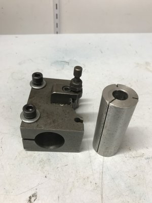
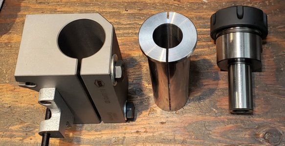
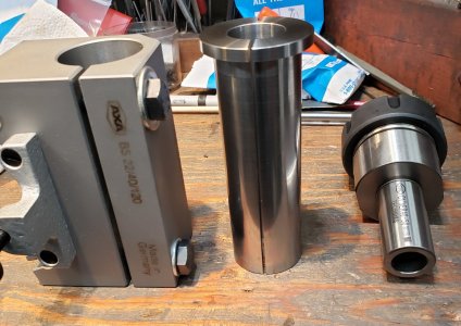
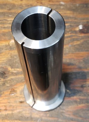
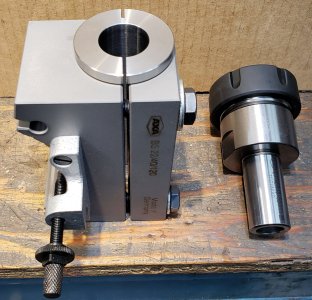
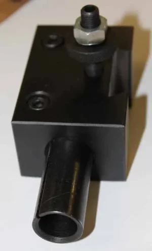
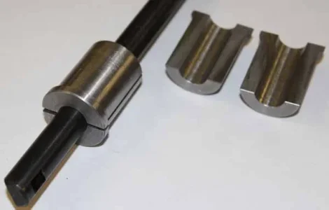
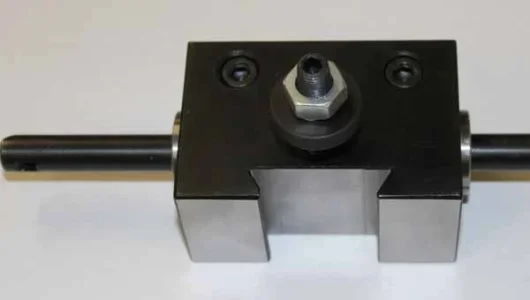
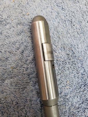
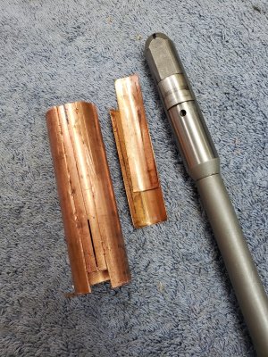
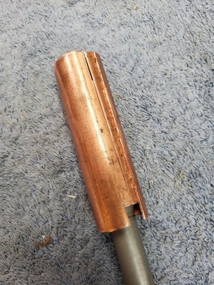
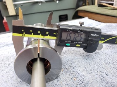
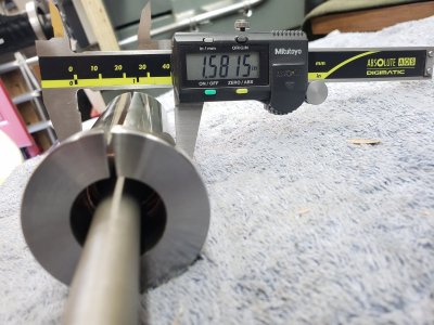
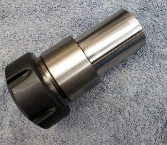
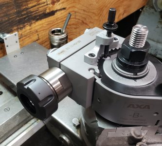
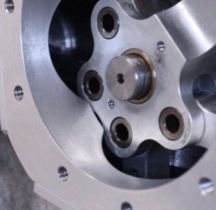
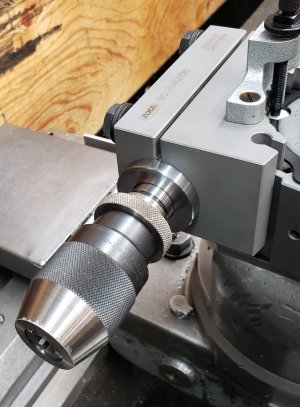
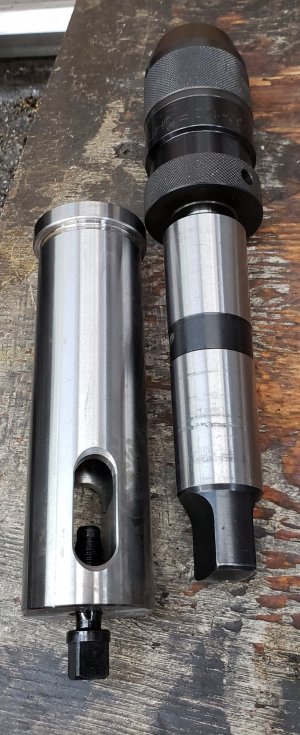
Can you post a few different views of this bushing you made? I can't really see how a split bushing could gall as you describe. I'm thinking maybe I don't really know what the split bushing looks like.
Can you post a few different views of this bushing you made? I can't really see how a split bushing could gall as you describe. I'm thinking maybe I don't really know what the split bushing looks like.