• Scam Alert. Members are reminded to NOT send money to buy anything. Don't buy things remote and have it shipped - go get it yourself, pay in person, and take your equipment with you. Scammers have burned people on this forum. Urgency, secrecy, excuses, selling for friend, newish members, FUD, are RED FLAGS. A video conference call is not adequate assurance. Face to face interactions are required. Please report suspicions to the forum admins. Stay Safe - anyone can get scammed.

Mystery lathe, for real

I'm pretty sure the lathe is metric threaded but I'm getting numbers that don't make sense to me.
I haven't much experience with trapezoidal metric threads but the metric measurement just don't look precise enough.
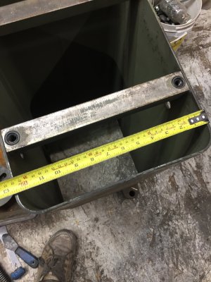
I used my most accurate digital calipers for the measurements, what do you guys think?
No, it is imperial. Both cross and compound lead screws are 10 tpi but the cross is 2-start, so one rotation is 1/5 of an inch, or 200 thou. That explains the marks on the dials -- graduations in thou on both, and radius, not diameter (for Sasquatch, I totally agree).
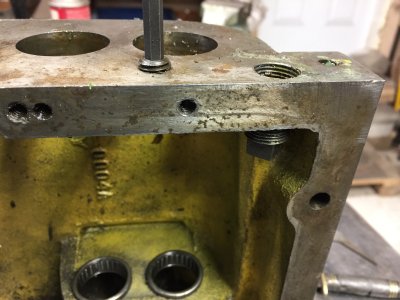
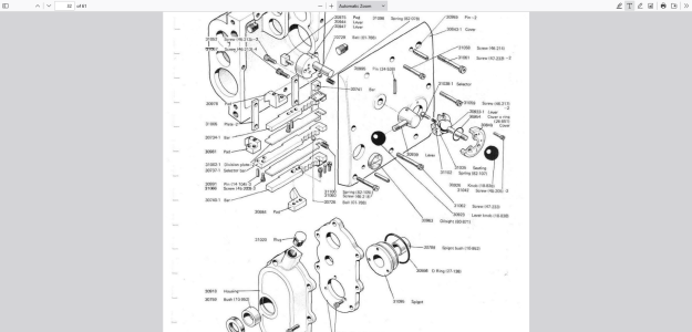
I THINK all the Bantams have power feed driven separately from the lead screw. Chipmaster does. You can see the feed data in the red boxes on the gearbox chart. When those gears are engaged, both the lead screw and the feed screw are driven, but unless you are cutting threads you are best to disengage the lead screw clutch just outside the gearbox to reduce wear on the thrust bearings. The note '1/2' just showing in your second picture advises that cross feed goes at 1/2 the speed of the longitudinal feed, which is stated in the appropriate box.
I also THINK the Bantam can only power feed toward the headstock and toward centre on the cross. Chipmaster can be reversed, which is kind of handy for threading away from the chuck (for example, managing a tight shoulder thread termination) though there are other ways to do that.
 
Thank you gentlemen, I appreciate the explanation. I've not done a lot of threading before and I guess it shows.

This lathe came with the single speed motor so there is 8 speeds from 36 rpm to 800 rpm, can I simply replace the 1750 rpm motor with a 3400 rpm motor so lowest speed would be 72 rpm and highest speed would be about 1600 rpm?
I can't say I have ever needed a speed lower than 400 rpm but 1600 would be useful at times.

I started disassembling the threading gear box yesterday, this machine has done a lot of threading in the past so will need to replace a few worn out and broken gears.
One strange thing I came across, the fill plug for adding oil to the gear box is mounted inside the box so there is no way to add oil without removing the whole front cover.
I thought it might just be an assembling mistake at the factory but now I have seen a couple of other gear boxes online and they have the fill plug mounted the same way.
Pretty strange.
 

Attachments

  • IMG_1806.JPG
    IMG_1806.JPG
    1.6 MB · Views: 9
  • IMG_1810.JPG
    IMG_1810.JPG
    1.1 MB · Views: 9
  • IMG_1813.JPG
    IMG_1813.JPG
    1,002.8 KB · Views: 9
can I simply replace the 1750 rpm motor with a 3400 rpm motor
More likely a 3600 rpm motor. But yes this is exactly what I did and many others have done in the past.
At that point a 150$ VFD would compliment your new motor ( would have to be 3 phase )
Nice to dial in some speed when parting off, I enjoy my vfd on both my mill and lathe.

Gluck
 
This lathe came with the single speed motor so there is 8 speeds from 36 rpm to 800 rpm, can I simply replace the 1750 rpm motor with a 3400 rpm motor so lowest speed would be 72 rpm and highest speed would be about 1600 rpm?
I can't say I have ever needed a speed lower than 400 rpm but 1600 would be useful at times.

If you thread, you will want low speeds. My lowest speed is 70. I would die to have 36. It is so important to have a low speed that I bought a 3ph motor and a VFD to get it. Until they are installed, my practice has been to stop the motor and then turn the chuck by hand as I approach a shoulder. I do not like crashes......
 
Well I'm not so sure now about this lathe never seeing a high school, I found some flaky repairs in the threading gear box that scream of high school.
When I started dismantling I found the woodruff key was missing on this gear, who knows what happened to it, so all that was left was a little set screw on the opposite side of the gear to hold it in place.
That set screw sheared off and remained buried in the shafts teeth, when they went in to fix the problem all they did was install a new set screw but still missing the woodruff key.
So that set screw sheared off as well, I suspect that's when threading stopped being done on this lathe.
In one of the pics the little screw driver is pointing to the other broken set screw.

I was mistaken about the fill plug being backwards, found the fill plug a bit lower down.
It is only 3/8", a little small compared with the 1/2" drain plug, I might drill that out and install a 1/2" npt instead.

It took a while to get the oil level sight glass clean, had to let it soak in carb cleaner then stuffed a bit of cotton in there and swab the surfaces down using a dental pick.
 

Attachments

  • IMG_1842.JPG
    IMG_1842.JPG
    861.7 KB · Views: 7
  • IMG_1844.JPG
    IMG_1844.JPG
    762.8 KB · Views: 7
  • IMG_1845.JPG
    IMG_1845.JPG
    799.3 KB · Views: 7
  • IMG_1847.JPG
    IMG_1847.JPG
    938.5 KB · Views: 7
  • IMG_1820.JPG
    IMG_1820.JPG
    1.3 MB · Views: 7
A few miscellaneous comments to add to recent posts. There has to be an external fill plug -- I was going to take a picture of mine but see you found it. Not sure what that internally threaded plug is for, actually. Is the hole possibly threaded for 1/2 pipe from both directions? If not, there should also be another drain plug. If you can't find it, I'll snoop around on mine and send a photo. You don't need a huge diameter fill plug, and if you drill it out you won't be able to use the correct filler fitting. It is nice to drain in more of a gush for the flushing effect.

For the motor, I 100% recommend going three phase with a VFD if you only have single phase, which accounts for most of us. You need low speed for threading, as Sasquatch has pointed out, and you also need some grunt at those lower speeds. A decent motor with VFD has that grunt, and a very low and sharp drop off of torque. You can also overspeed the motor to get spindle speeds higher than 800 you have now which you may quickly find you need for decent surface finish on small -ish parts which is what you are going to use this lathe for. A lot of Bantams seem to have come with a two speed motor and top spindle RPM double the 800 you are reporting. If you go for a fast 3 phase motor and use the VFD to access lower speeds, with torque, that may be the best compromise. FWIW, my chippie tops out at 3000 rpm spindle speed and I am finding myself more and more using the upper range speeds as I learn what the cheap carbide inserts that I run can and can't handle. It is not about saving time, it is about getting an insert to cut smoothly and break chips. This isn't limited to carbide, but more obvious when you use it. My slowest speed is 35 rpm in back gear. I usually fuss around with the speed when threading and often end up in the 50-75 rpm range for up to 1/2 inch diameter. Kind of the sweet spot for finish vs my nerves if the job involves a shoulder or tricky pull out without a gutter.

Before spending money sourcing a lot of replacement gears or paying to have them made, I would fix the obvious issues then pack it up and run it. A lot of lathes seem to work just fine with some pretty appalling looking gears -- they might be noisy but a slow speeds, you can live with it at least for a while and until you find the other gremlins lurking like alignment, bed wear, gib wear and etc.

Check that the shear pin (it must have one) is soft. Previous owner may have done you a 'favour' and installed a dowel pin or smooth end of a drill. While getting to know the machine, a brass pin might be advisable.

My understanding is that the Bantam was a very capable machine in its day, so that means to this day as well. Maybe not ideal for making aerospace parts, as they say, but very capable and worth the effort to save it and use it.
 
Here is the fill and drain setup on a late model chipmaster. The fill is at the top rear of the gear case; a street elbow and vented plug. The drain is at the bottom front. It would drain into the chip pan if I was feeling lazy. The drain appears to be 3/8 NPT but the fill looks somewhere in between 3/8 and 1/2 NPT but of course that makes no sense. It looks to be something proprietary, but I'm sure a simple street elbow would work just as well. The vent is probably important.
 

Attachments

  • IMG_5298.JPG
    IMG_5298.JPG
    2.1 MB · Views: 4
  • IMG_5300.JPG
    IMG_5300.JPG
    1.6 MB · Views: 4
  • IMG_5299.JPG
    IMG_5299.JPG
    1.9 MB · Views: 4
British pipe fitting generally have the same tpi as American except they are straight instead of tapered. Europeans use the British standard as well . We would use a lot of Teflon tape in dealing with the piping on the machines.
 
Here is the fill and drain setup on a late model chipmaster. The fill is at the top rear of the gear case; a street elbow and vented plug. The drain is at the bottom front. It would drain into the chip pan if I was feeling lazy. The drain appears to be 3/8 NPT but the fill looks somewhere in between 3/8 and 1/2 NPT but of course that makes no sense. It looks to be something proprietary, but I'm sure a simple street elbow would work just as well. The vent is probably important.
Interesting, I figured out the real fill port, the drain on mine is in the same place as yours but there is this narrow secondary gear housing to the left of the main threading gear box.
The fill cap is vented and the oil flows through six 1/4" holes in what Colchester calls a spigot, it supports the oil slinger and the bottom gear shaft.
There is also a vent at the top of the main gear box as well.
 

Attachments

  • IMG_1852.JPG
    IMG_1852.JPG
    934.5 KB · Views: 6
  • IMG_1853.JPG
    IMG_1853.JPG
    969 KB · Views: 4
  • IMG_1854.JPG
    IMG_1854.JPG
    1 MB · Views: 3
  • IMG_1868.JPG
    IMG_1868.JPG
    1 MB · Views: 4
  • Screenshot 2025-03-31 at 16-43-52 colchester_bantam_full_manual.pdf.png
    Screenshot 2025-03-31 at 16-43-52 colchester_bantam_full_manual.pdf.png
    637.8 KB · Views: 5
Interesting, I figured out the real fill port, the drain on mine is in the same place as yours but there is this narrow secondary gear housing to the left of the main threading gear box.
The fill cap is vented and the oil flows through six 1/4" holes in what Colchester calls a spigot, it supports the oil slinger and the bottom gear shaft.
There is also a vent at the top of the main gear box as well.
Ok, this all make sense now. The main gearbox casting 1441 is common to various models, including the Chipmaster, but the latter is belt driven. That backwards plug you found, and showing upper left in your EPD in the last post plugs the port that is used for the fill elbow on my lathe. See my EPD below. The drain is going to be identical, out the lower front. Because your lathe is gear driven, there is an exterior gearbox 30918 bolted to the rear of the main gearbox on the Bantam and holding the driving mechanism (a toothed belt on mine) and you load the lube oil through that housing at the top. Another difference is I have a 9-position cylindrical tumbler sticking out the front, while you have a 6 position selector handle on the front cover. This means the front cover for the gearbox is different. This has implications for sourcing spare parts, obviously. The Bantam gearbox is identical in some ways, but very different in others. Some parts would interchange, however.
You are making great progress there to pull it all apart in order to understand the design and refurbish as required. Very interesting.
 

Attachments

  • Screenshot 2025-03-31 at 4.03.36 PM.png
    Screenshot 2025-03-31 at 4.03.36 PM.png
    447.4 KB · Views: 2
Back
Top