• Spring 2024 meetup in Calgary - date Saturday, April 20/2024. discussion Please RSVP Here to confirm and get your invitation and the location details. RSVP NOW so organizers can plan to get sufficient food etc. One week to go! More info and agenda
  • We are having email/registration problems again. Diagnosis is underway. New users sorry if you are having trouble getting registered. We are exploring different options to get registered. Contact the forum via another member or on facebook if you're stuck. Update -> we think it is fixed. Let us know if not.
  • Spring meet up in Ontario, April 6/2024. NEW LOCATION See Post #31 Discussion AND THE NEW LOCATION

My "New" Lathe

JohnW

(John)
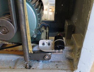
Here is the next part of the brake mechanism. This is looking through the left hand pedestal from the end. You can see the brake lever from the previous post in the opening. This picture was taken before the braking resistors were installed. They would be in the upper right corner of this picture. I made up a new bracket to hold the brake switches. Originally there was only one switch and it used a bit of an ugly bracket that was mounted a bit further to the left than my new switches. The big spring is what keeps the brake held in the off position.
BrakeSwitches_3725.jpg

Here is a close-up of the switches and the brake lever. I added the tab on the right side of the lever to actuate the switches. The switches are setup up to provide two signals depending on how far the brake lever is pushed. The right hand switch clicks with the slightest movement of the lever. That way a light tap on the brake lever will tell the lathe to stop and use a normal decel curve (2-secs). A light tap is not enough to actuate the physical brake. The physical brake is applied by pushing the yellow bar up. Look way back to an early posting in this thread to see what happens up there.
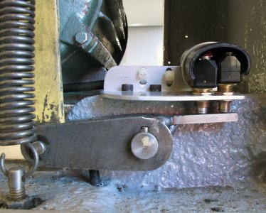
BrakeSwitches_3727.jpg

Pressing harder on the brake lever will actuate the physical brake and the left hand switch. That switch sends a DC braking signal to the VFD telling it to stop as quickly as it can.

The micro-switches have a short piece of (split open) plastic tubing tie-wrapped over them to protect them from stuff falling on them. If a big metal filing were to fall on top of them it could short the contacts, so this way that will not happen. The extra holes in the bracket are used as a stress relief for the cable running back to the control box.

So the manual brake works as follows:
  • Press it lightly to stop the motor normally using a 2-second ramp-down. To restart, the FNR lever must be returned to N and then to F or R.
  • Press it hard to both apply the physical brake and tell the VFD to stop the motor as quickly as possible. This is the real emergency stop mode since it is way more effective than just killing the power. The lathe is stopped as quickly as possible in this mode.
  • Use this hard press on the brake for emergency stops, and to quickly stop when machining up to a shoulder

Here is the wiring diagram for the brake switches:
 

Attachments

  • Electrical Controls and Schematics_BrakeSwitches.pdf
    52.8 KB · Views: 2

PeterT

Ultra Member
Premium Member
So relating to my example of threading up to a defined shoulder (ie. a position on the work that you don't want the cutting tool to cross over). Could you set up a limit switch ahead of the shoulder position so that when it sees the carriage arrival, it initiates a defined ramp-down in the VFD? Lets say it didn't even have to be a rapid stop, something conservative like 2 seconds. If I understand correctly, could you could still reliably count on this same zero rpm stop position for each repeated threading pass? Maybe you would have to tweak the sensor position with a few dry run passes to ensure the cutter point comes to a stop inside the target relief groove. Or maybe knowing rpm, time & thread pitch you could figure out the position. Anyway if it works this way, it would eliminate the typical threading disengagement lever pulling rigmarole, no?

The VFD can be told to use whatever acceleration curves you want. For most operations, I have mine set to a 2-second ramp up/down which I think is a reasonable compromise between waiting for speed to change, peak power usage, and wear and tear on mechanical things. When deceleration is triggered by the brake switch on my machine, it switches to a 0.5s ramp down. The bottom line is I will only use the brake lever when I really want it to slow down. In normal stops, the 2s ramp down is fine.
 

JohnW

(John)
Peter:

Yes you could do that. If the standard decel would work for you, the sensor switch could just break the motor-enable circuit (I will post the full schematic soon), and that would immediately initiate a 2-second decel. Alternatively, you could change the decal to 0.5sec or something more aggressive and do the same thing. It should be pretty consistent as to where it stops given the same RPM, chuck and work piece. It is easy to reprogram the decal rate for a use like this, and put it back when you are done.

You do need to be careful in stopping a carbide bit (if you are using that) while it is engaged. I have broken more than one by stopping in the middle of a cut. It seems to put a ton of stress on the bit as it comes to a stop and "ping" off comes a corner of the cutter.

The only problem with doing this in my set-up is that I've already used up all of the VFD input interfaces to do other things like F/R job, braking, etc. If you override one of the other inputs temporarily it is certainly possible to do.

If you wanted to be a bit fancier, the VFD can also be programmed and ordered around via an RS485 interface. An Arduino microcontroller could easily be programmed to interface to the VFD on the RS485 interface (RS485 is an industrial version of the RS232 interface that is often used by PC's and less industrial stuff). The RS485 interface can tell the VFD to do all sorts of things that override what the normal inputs do.

You could, for instance, use two limit switches. The first senses when you are maybe 1/4" from the end which would then ramp the VFD down to minimum speed over maybe 1 second. The second might only be 0.010" from the end, and tell it to stop as quickly as possible, which would happen very fast from a slow speed.
 

PeterT

Ultra Member
Premium Member
Yes, that's what I've heard about carbide threading inserts in particular. The don't like sudden load interruptions like entering an existing thread with too much in-feed. They don't like stopping mid cut. And they typically like to run at higher speeds. All of these factors collectively working against you on a manual lathe. One more for good measure - metric threading on an IMP machine, most say don't disengage the threading half nuts.

I figure 99% of all external & internal thread jobs should have a relief groove incorporated on one side (meaning slightly deeper than the maximum thread depth). So if a VFD could be controlled to reliably terminate when the V point is inside the groove, that would be a very desirable feature over & above the VFD speed control advantages.
 

JohnW

(John)
So now its time to get heavier into the electrical controls. After thinking about all the controls and switches, I designed the electrics. The actual order was:
  1. Fwd / Rev switches - This was pretty obvious 2 micro-switches and an 8-conductor cable back to the control box. I used 8 wire cable when I only needed six because I had some very flexible, shielded, and tough 8-conductor cable that was ideal for this.
  2. Brake Switches - I know I wanted to detect the two braking stages, so again, two micro-switches, and 6 conductors back to the control box in an 8-conductor cable. I'd figure out how to make it work later.
  3. Once I was getting close to having most things rebuilt, I read the VFD manual several times, scratched my head for a while, and designed the overall schematic.
  4. The VFD has 10 low voltage connections, so I ran a 12 conductor cable between the VFD and the control box. It is always a good idea to have a couple of extra conductors.
  5. Once I had what I thought would be a working schematic, I found a way to arrange all the required components and terminal strips required on the original phenolic board that fit in the original wiring box for the lathe.
  6. I drew up the schematic and all the connections using Visio. This is complex enough that if I ever needed to look at it again in a couple of years, I would need it all documented. Just to get the wiring right in the first place it was a good idea to have nice readable schematics to help me keep everything straight. I still made a couple of small mistakes!
  7. Then I wired up the internal control board connections.
  8. Finally, I installed the control board and connected it to all the wires that came in from the various external devices.
  9. Set all of the VFD parameters to what I thought was the correct settings to make all of this work.
  10. I tested it, found a couple of mistakes, and fixed them. Nothing serious here, I mixed up a couple of wires from the NC and NO contacts on a couple of micro-switches.
  11. I spend some time tuning up various parameters in the VFD. It didn't all work out as I had hoped, but the major functions were fine. The only real issue was that I could not get reverse JOG to use a low frequency, or a different acceleration ramp. The result is that reverse jog is really just another easy way to select reverse momentarily, instead of reverse at a low speed. I can live with that.
So, here are some photos:

First, the control board. The left and upper portion (mainly black stuff by coincidence) is 120V and 240V stuff. The main 240V single phase input comes into the fuse block on the upper left. The power output to the VFD leaves on the terminal strip on the far left.

There is a small 1.6A breaker in the fuse block that provides current to the 120V portion of the control circuits from one of the input phases. That way any issue with the 120V control circuits doesn't end up in a huge (nasty and probably exciting) short circuit fed from the 30A slow-blow fuses, but instead quickly opens up the 1.6A breaker. That circuit needs far less than 1A to operate.

The big relay is the main power on/off relay (it was one of the originals from the lathe), and the smaller relay in the upper right is a 120V relay that is used to de-latch the main relay.

The longer black terminal strips are where various 120V things connect.

The smaller white terminal strips are used to connect to the various low-voltage controls. All of the terminal strips are raised up on HDPE strips to make room for the wiring to run around below them. That way it is easier to install the external wiring on top of it all.

There are also two other breakers that are mounted on the control box itself:
  • A 7A breaker controls the auxiliary 120V circuits, which includes the coolant pump, the rear auxiliary plug that supplies some additional lights and the DRO AC adapter, and the 20V supply for the fan.
  • A 2A breaker on the 20V DC circuit that supplies the cooling fan, and some future electronics that I have planned.
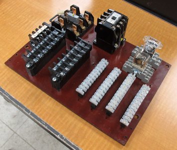
So, here is the unwired control board:
Control Board_5356.jpg

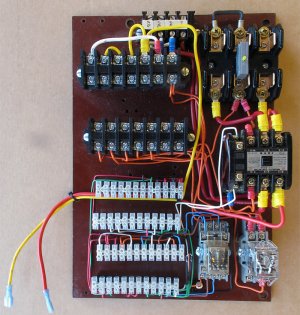
And the control board with the internal wiring installed. The red and yellow wires hanging off the side go to the 7A AC breaker.
ControlBoard_5953.jpg

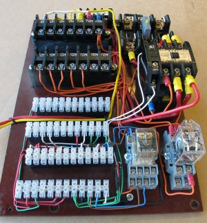
Another view of it. I tried to use wires of the same color to control similar portions of the circuit. The smaller relays are mounted in terminal blocks, so they can be removed easily and have nice screw terminals.
ControlBoard_5955.jpg

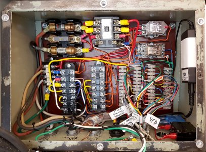
And what it looked like once it was installed in the control box and connected up. I installed 1/4" nutserts to hold the cover on instead of the sheet metal screws that were originally used. The 20V supply is mounted on the right side, the 120V 7A breaker and the 20V 2A breaker are mounted on the lower right.

All of the wiring comes up from the bottom, with either the hole labeled as to what is coming in there, or where several low-voltage cables come in together, there are labels on each cable to identify it. Nothing really fancy here, just white electrical tape, and a quality permanent marker (Staedtler).

The high voltage stuff is on the left, and the low voltage stuff is on the right. It is always a good idea to separate the high and voltage stuff as much as possible when they are combined in a box.

The white/black/green harness that exits out of the bottom of the picture goes to a 3-pin connector that connects to the 120V plug that is mounted on the cover. The connector allows the cover to be removed instead of hanging by the wires.

Some judicious use of wire ties keeps it reasonably neat.
ControlBoard_Wired_20180325_114617.jpg

I've attached a PDF of the layout document I created for the control box.

The next post will go into detail on the high voltage wiring.
 

Attachments

  • Electrical Controls and Schematics_ControlBoardLayout.pdf
    358.5 KB · Views: 5
Last edited:

JohnW

(John)
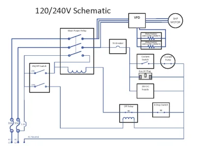
Here is the schematic for the high voltage (240/120V) circuits. I've also attached a higher resolution PDF of this.
Electrical Controls and Schematics_HighVoltageSchematic.png
  • The 240V spilt phase AC comes in via a standard stove plug that is connected to a pair of 40A breakers in the panel. The connections to L1, L2 and Neutral come in on the bottom left.
  • The first thing in the circuit is a pair of 30 slow blow fuses that protect everything. Those two circuits go to the main contacts on the big relay (aka contactor) and then on to the VFD. There are three wires connected to the VFD, since it is a 3-phase input VFD. Two of the phases are connected together. There are a couple of reasons to do it this way:
    • Some 3-phase VFD's will signal a fault if one of the three input phases is dead. That is a good thing if you are connected to 3-phase power. In that case you want to know if you have a dead phase. Connecting the extra input like this will usually fool the VFD.
    • It makes life a little easier on the VFD in that two of the sets of input rectifiers will share the load. The third still needs to take the full load. That is not a big difference, but you may as well do it since it is easy.
    • The VFD needs to be de-rated by something like 30% in this configuration since it is only receiving power pulses from the AC line 120 times a second instead of the 360 times a second it would receive with a 3-phase input. That puts more load on the input diodes and the DC bus capacitors. I will likely never run the lathe hard enough for this to be an issue.
  • The braking resistors simply connect to the VFD. The VFD controls them. Nothing fancy there.
  • The three phases from the VFD are fed out to the 3-phase motor. Again pretty straight forward. The VFD controls the motor based on signals form the low-voltage signals that are connected to it.
  • One of the phases from the main relay feeds a 7A breaker that runs the coolant pump (via the front panel switch), the 20V DC supply and the auxiliary plug. Again , pretty straight forward. That means that one leg of the input 240V will be loaded a bit more than the other, but only by a couple of amps, so it is not a big deal.
  • The main relay control is a bit more complex:
    • The control circuit is protected by a 1.6A circuit breaker. That allowed me to use relatively thin wires in this circuit. Also since these wires head up to the control panel, if there were ever a problem, there would not be a lot of current involved. This circuit uses a maximum of less than a quarter of an amp, so the 1.6A breaker I happened to have around is more than enough and small enough to protect the control circuit.
    • The "on" side of the main power switch on the front panel will energizes the relay when it is pulsed.
    • The relay will then latch on because the lower of the three contacts will feed power back to the coil once it has been energized.
    • The power in the relay coil has to go through two other devices before the relay can be (or stay) energized:
      • The E-stop switch. If the e-stop switch is opened, it will not allow the relay to close, and if the relay is already closed, it will remove the power and the relay will open and shut down all the power.
      • The Off-relay is normally closed, but is opened by a pulse from the front panel off switch. Once it opens the main relay releases and power is turned off.
And that's it for the high voltage control. The important thing here is that the main relay will release if there is a power failure, or if the e-stop switch is pressed. When it is released there is no power being consumed by the lathe.

I had thought about a pilot light to indicate that the power is on, but did not bother because the VFD display indicates that the power is on. Still, it would not have been too bad an idea to put a pilot light on the main panel.
 

Attachments

  • Electrical Controls and Schematics_HighVoltageSchematic.pdf
    68.3 KB · Views: 2
Last edited:

JohnW

(John)
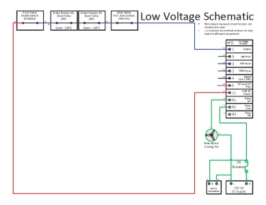
Now on to the low-voltage schematic. This is a lot more complicated, so I will present it in several stages. Here is the schematic for the VFD enable circuit, and the cooling fan circuit. Electrical Controls and Schematics_LowVoltageSchematic_Enable-Fan.png
The VFD is controlled by a 24V circuit that it provides the power for (VFD terminal 11). The VFD cannot provide a lot of power on this circuit (maximum 100ma), but that is more than enough for what I am doing here.

The VFD Enable input (terminal 1) must be connected to 24V for the VFD to run the motor. The VFD is programmed to provide a normal decel ramp when the enable line is disconnected. It also provides a safety function such that if Enable and a motor run command (i.e.: Fwd, Rev, or Jog) are both present at power up or when Enable is activated, that it will not run the motor until the motor run command has been removed. That prevents the motor from unexpectedly running.

The enable circuit is quite simple. Since it is a normally closed loop (all switches must be closed and the wiring must be intact), any wiring problem will disable the motor until the problem is repaired. Failing off is much safer than the possibility of failing on. It is a series circuit including the following.
  • The front panel Motor Enable switch,
  • The two brake resistor over temperature sensor switches. This is a safety circuit that will prevent the motor from running if either of the brake resistors is too hot. The thermal switches will open long before the resistors are dangerously hot, they should still have the capacity to help in one more stop if the motor is currently running and the VFD tries to stop it using the braking resistors. The VFD will not run the motor again until the resists have cooled again. The thermal switches have a hysteresis of about 30C, so they will turn off at about 130C, but not turn on again until they cool to below about 100C.
  • An auxiliary contact on the main power relay. This means that if the main relay is de-energized, that the VFD will also stop powering the motor. It won't be able to continue to power it for long if the motor was running since it will have had its power removed as well, but it does have some large internal capacitors on the DC bus. If the motor is not running when the main relay turns off, this prevents the VFD from executing any motor run commands. This is really not a very important function, but I had an extra contact on the main relay so I used it to signal the VFD.
The motor fan circuit is also quite simple:
  • The VFD has an internal relay that is programmed to be turned on whenever the VFD is providing power to the motor.
  • The motor cooling fan is powered by the 20V supply and turned on whenever the VFD internal relay is turned on.
  • I would have liked to have the motor cooling fan stay on for 30 seconds after the motor has run, but there was no VFD option to do that and I did not think it was important enough to design a delay circuit for that.

The "Instrumentation" box is some future electronics I have planned to provide a digital readout on what the lathe is up to. It is not installed yet.
 

JohnW

(John)
Nope. The VFD does not use a neutral line. It strictly connects to the 3 hots in a 3-phase system, or the 2 hots in a spilt phase system.

If you are referring to the two lines leading from one contact on the main relay to the VFD, that is somewhat explained in the text. Since it is a 3-phase VFD, I have all three phases connected to the two hots that are available. Some 3-phase VFD's will complain if one of their phases is not live, but they are generally not smart enough to detect that two of the phases are identical, or that they are really only receiving single phase power with the phases 180 degrees apart instead of 120 degrees apart as they should be in a 3-phase system.

The diagram does show how the lathe is wired. There is a 4-wire cable running from the control box to the VFD:
  1. Phase-1 - Black - Input line-1
  2. Phase-2 - Red - Input line-1
  3. Phase-3- White - Input Line-2 - Should have blue tape on this wire to indicate it is hot, and not actually a neutral.
  4. Ground - Green - Ground.
The second line off the other main relay terminal goes out to the 7A breaker for the auxiliary 120V circuit. Since that is a 120V circuit, it returns to neutral.

Update: added 3rd paragraph.
 
Last edited:

Johnwa

Ultra Member
The drawing shows 3 wires going into the vfd. I think he was referring to the two wires off the top power relay terminal.

I’m early in the process of properly wiring up my vfd. I wasn’t planning on an e-stop that shuts off all power. I’m now rethinking that plan.
 

JohnW

(John)
OK, so on to low-voltage schematic part 2:
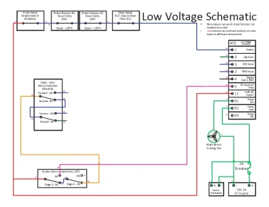
Electrical Controls and Schematics_LowVoltageSchematic_Brake.png
I've added the brake switches and the Fwd/Rev switches to this diagram.
  • The 24V signal goes through the NC (normally closed) contacts of both brake switches to feed the F/R switches.
  • If either switch is open (the brake is pressed), the power is removed from the F/R switches, which will remove any forward / reverse / jog signal being given to the VFD.
  • If the brake lever is pressed lightly, only the stage-1 switch will open, which removes any go signal from the VFD as described above. If the motor is running it will ramp down to a stop since the VFD is just seeing its go signal being removed.
  • If it is pressed further, the stage-2 NC switch will open and connect 24V to the NO contact. That will then send a signal to the VFD DC Injection Stop terminal (#6). When the VFD sees that, it uses DC injection to bring the motor to a stop quickly. With that and the physical brake, the motor comes to a stop very quickly.
Here is a great benefit of documenting what you do. In re-reading this post, I realized that the brake switch contacts are actually labeled wrong here, the description above is also wrong. The NC and NO labels should be reversed. The brake switches normally sit partially pressed in, so their NO contacts are closed and the NC contacts are open. When the brake lever is pressed, one or both of the switches will be released moving the switches to their NC positions. I will update the diagram and re-post it.

Sorry!
 
Last edited:

RobinHood

Ultra Member
Premium Member
Excellent write-up! This is a great tutorial for someone wanting to go down the same road and improve the wiring on their lathe.
 
Top