-
Scam Alert. Members are reminded to NOT send money to buy anything. Don't buy things remote and have it shipped - go get it yourself, pay in person, and take your equipment with you. Scammers have burned people on this forum. Urgency, secrecy, excuses, selling for friend, newish members, FUD, are RED FLAGS. A video conference call is not adequate assurance. Face to face interactions are required. Please report suspicions to the forum admins. Stay Safe - anyone can get scammed.
-
Several Regions have held meetups already, but others are being planned or are evaluating the interest. The Calgary Area Meetup is set for Saturday July 12th at 10am. The signup thread is here! Arbutus has also explored interest in a Fraser Valley meetup but it seems members either missed his thread or had other plans. Let him know if you are interested in a meetup later in the year by posting here! Slowpoke is trying to pull together an Ottawa area meetup later this summer. No date has been selected yet, so let him know if you are interested here! We are not aware of any other meetups being planned this year. If you are interested in doing something in your area, let everyone know and make it happen! Meetups are a great way to make new machining friends and get hands on help in your area. Don’t be shy, sign up and come, or plan your own meetup!
You are using an out of date browser. It may not display this or other websites correctly.
You should upgrade or use an alternative browser.
You should upgrade or use an alternative browser.
My "New" Lathe
- Thread starter JohnW
- Start date
JohnW
(John)
Its been a long time since I've posted any progress on this project, although I have actually done some stuff on the project over the last two years. . . .
I've added a coolant pump. Busy Bee had a 220V coolant pump and reservoir on sale about 2 years ago - I think it was significantly less than $200.
https://www.busybeetools.com/products/coolant-pump-for-metal-working-mach-csa-b3087.html
They call it a 5 gallon reservoir, but that is only true in some other reality. Realistically, it can hold maybe 8 liters of coolant. The tank is a double reservoir design, so filings and metal bits can settle in the first tank, then the coolant overflows to the second tank where the pump picks it up without recycling too much junk.
I wanted to run mine on 120V instead of the 220V it is listed at, since it fit my wiring plan better. I did some web research and this pump is made (or imported) by Flair America (flairamerica.net). It seems to be one of the MC-81xx pumps which are available in 120V and 220V models.
I took the BB pump apart to see how the motor is wired. It is a simple 1/8 HP induction motor. The field coils are two identical 120V coils wired in series to operate at 240V. That is what I had expected since they probably really only make one motor with slightly different wiring for 120 or 240V. I changed the wiring to put the field coils in in parallel for 120V operation. I was careful to keep the phasing the same, and now it is 120V motor. So, problem solved. I added a cord with a regular plug on it. It doesn't look like I took any pictures of that operation, so you have to trust me.
I used some scrap aluminum (from an old computer monitor bracket) to make a bracket to hold the drain tube from the chip tray in the correct spot. You are looking at a couple of my first non-practice aluminum TIG welds here. I had to machine out the hole in the bracket to be a bit larger to hold the tubing, so there is some machining content here.
It would make a real mess if the return tube (from the bottom of the chip pan) decided to come out of the filter basket, so this bracket will ensure that it will stay put. I then added a drain and a valve to the bottom of the reservoir so it is easier to change the fluid in the future. Without the drain, you'd have to hold it upside down while it made a mess draining out from the big hole. It seems I can never leave well enough alone!

When I was re-assembling the main lathe pieces a while ago, I cut an opening in the right hand side pedestal so I could easily get in there from the front. Of course, the hole was not quite large enough for this reservoir, so I had to make the opening a bit wider. Also here you can see the angle iron I added to make a base inside the pedestal. 15 minutes with a metal cutting blade in a saws-all with a few daubs of paint, and the opening looked like I had intended on doing that in the first place. No one (except the whole Internet) will ever know.

I installed the rear cover and a piece of painted MDF on the bottom (you can see that on the RHS of the image), and sealed it up with silicone so if some coolant leaks, it will come out the front instead of all the places where it is almost impossible to clean up.
Here is the completed pedestal with the coolant pump installed. There is a plug installed on the top of the pedestal where the coolant pump plugs in. That plug is switched with a switch on the front control panel of the machine (more on that soon). The only thing left to do here is make a cover and attach it with a few magnets. The little hose on the bottom drains anything that might spill or leak in the pedestal, so I will hopefully notice it before it makes too big of a mess when the cover is installed.

Up top, I added some plumbing that connects up to the vinyl tube that runs up with the DRO wiring (see a previous post). I used a simple air fitting attached to the carriage (hopefully that will work OK with water based coolant). I then used an old magnetic dial gauge stand I had hanging around and made bracket to hold a piece of tubing and connected up a valve to control flow and a nozzle that can be moved around to direct the coolant wherever I need it.

I've added a coolant pump. Busy Bee had a 220V coolant pump and reservoir on sale about 2 years ago - I think it was significantly less than $200.
https://www.busybeetools.com/products/coolant-pump-for-metal-working-mach-csa-b3087.html
They call it a 5 gallon reservoir, but that is only true in some other reality. Realistically, it can hold maybe 8 liters of coolant. The tank is a double reservoir design, so filings and metal bits can settle in the first tank, then the coolant overflows to the second tank where the pump picks it up without recycling too much junk.
I wanted to run mine on 120V instead of the 220V it is listed at, since it fit my wiring plan better. I did some web research and this pump is made (or imported) by Flair America (flairamerica.net). It seems to be one of the MC-81xx pumps which are available in 120V and 220V models.
I took the BB pump apart to see how the motor is wired. It is a simple 1/8 HP induction motor. The field coils are two identical 120V coils wired in series to operate at 240V. That is what I had expected since they probably really only make one motor with slightly different wiring for 120 or 240V. I changed the wiring to put the field coils in in parallel for 120V operation. I was careful to keep the phasing the same, and now it is 120V motor. So, problem solved. I added a cord with a regular plug on it. It doesn't look like I took any pictures of that operation, so you have to trust me.
I used some scrap aluminum (from an old computer monitor bracket) to make a bracket to hold the drain tube from the chip tray in the correct spot. You are looking at a couple of my first non-practice aluminum TIG welds here. I had to machine out the hole in the bracket to be a bit larger to hold the tubing, so there is some machining content here.
It would make a real mess if the return tube (from the bottom of the chip pan) decided to come out of the filter basket, so this bracket will ensure that it will stay put. I then added a drain and a valve to the bottom of the reservoir so it is easier to change the fluid in the future. Without the drain, you'd have to hold it upside down while it made a mess draining out from the big hole. It seems I can never leave well enough alone!
When I was re-assembling the main lathe pieces a while ago, I cut an opening in the right hand side pedestal so I could easily get in there from the front. Of course, the hole was not quite large enough for this reservoir, so I had to make the opening a bit wider. Also here you can see the angle iron I added to make a base inside the pedestal. 15 minutes with a metal cutting blade in a saws-all with a few daubs of paint, and the opening looked like I had intended on doing that in the first place. No one (except the whole Internet) will ever know.
I installed the rear cover and a piece of painted MDF on the bottom (you can see that on the RHS of the image), and sealed it up with silicone so if some coolant leaks, it will come out the front instead of all the places where it is almost impossible to clean up.
Here is the completed pedestal with the coolant pump installed. There is a plug installed on the top of the pedestal where the coolant pump plugs in. That plug is switched with a switch on the front control panel of the machine (more on that soon). The only thing left to do here is make a cover and attach it with a few magnets. The little hose on the bottom drains anything that might spill or leak in the pedestal, so I will hopefully notice it before it makes too big of a mess when the cover is installed.
Up top, I added some plumbing that connects up to the vinyl tube that runs up with the DRO wiring (see a previous post). I used a simple air fitting attached to the carriage (hopefully that will work OK with water based coolant). I then used an old magnetic dial gauge stand I had hanging around and made bracket to hold a piece of tubing and connected up a valve to control flow and a nozzle that can be moved around to direct the coolant wherever I need it.
Last edited:
Nice job John. My bandsaw has a very similar coolant pump and tank. Emptying it is a big pain and a mess. The drain is a good idea. Would you mind posting a couple close ups of the drain details? How do you keep it from leaking where it joins the tank?
My lathe also has the coolant coming up there beside the cross slide. I find the compound tends to back into it when trying to cut a taper. So I ended use removing the coolant wand and wondered what to do about that. I like your reuse of the mag base.
My lathe also has the coolant coming up there beside the cross slide. I find the compound tends to back into it when trying to cut a taper. So I ended use removing the coolant wand and wondered what to do about that. I like your reuse of the mag base.
JohnW
(John)
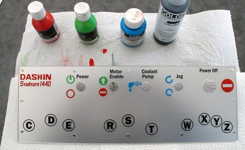
The next sub-project was making up a new front control panel for the machine. Here is what the original panel looked like. It had a couple of large switches, and the previous owner had moved the main power switch, which was originally awkwardly on the back of the machine to the front. Those are the holes over on the right hand side. The letters on the bottom are the labels for the feed gearbox levers.

Part of my plan is to use a VFD to power the motor and completely re-design the control wiring for the lathe so I needed to make a new control panel. Here is the new aluminum panel with the new switches installed. The aluminum is from an old sign.
The front:

And, the rear with the wiring installed. There is a bracket in the middle as a stress relief for the wires. The harness is tie-wrapped to the bracket so the wires are held solidly. You can see the countersunk screws that hold the bracket in the previous image. There are both 24V and 120V wiring here. The 24V circuits all go through the smaller shielded black wire, and the 120V wires are in the split loom. All 120V wiring has heat-shrink over the switch terminals so very little is exposed. When installed, the wire harness makes a loop, so there is room to remove the panel and pull it six inches or so away from the machine in case I ever need to get in there.

Here is where the control panel will be mounted. It is not in this picture, but I added a strip of 1/2" x 1/2" x 1/8" aluminum angle iron across the top of the opening to support the new control panel. The old one had no support there and moved a bit when pressing the buttons.

I have documented all of my wiring diagrams, and I will be posting them soon when I describe how I have the VFD and controls set up in more detail.
Edit: added the last picture.
Part of my plan is to use a VFD to power the motor and completely re-design the control wiring for the lathe so I needed to make a new control panel. Here is the new aluminum panel with the new switches installed. The aluminum is from an old sign.
The front:
And, the rear with the wiring installed. There is a bracket in the middle as a stress relief for the wires. The harness is tie-wrapped to the bracket so the wires are held solidly. You can see the countersunk screws that hold the bracket in the previous image. There are both 24V and 120V wiring here. The 24V circuits all go through the smaller shielded black wire, and the 120V wires are in the split loom. All 120V wiring has heat-shrink over the switch terminals so very little is exposed. When installed, the wire harness makes a loop, so there is room to remove the panel and pull it six inches or so away from the machine in case I ever need to get in there.
Here is where the control panel will be mounted. It is not in this picture, but I added a strip of 1/2" x 1/2" x 1/8" aluminum angle iron across the top of the opening to support the new control panel. The old one had no support there and moved a bit when pressing the buttons.
I have documented all of my wiring diagrams, and I will be posting them soon when I describe how I have the VFD and controls set up in more detail.
Edit: added the last picture.
Last edited:
JohnW
(John)
Would you mind posting a couple close ups of the drain details? How do you keep it from leaking where it joins the tank?
.
Well, hopefully it won't actually leak. I haven't added coolant yet. Here is what I did. Its been a while and I didn't take pictures. I just ran out to the shop and grabbed these pictures. Hopefully they will tell the story well enough. I'm pretty sure it will work OK.
I found this fitting in the plumbing dept at Home Depot. I'm not sure what it is really for. I think it came with a big nut and a rubber washer, so I bought two (I think this is the left over one). It was only a couple of bucks. From the pictures (I don't really remember), it looks like I cut off the large end and only used the treaded parts and the plastic nuts with rubber washers.

I drilled the hole in the tank and roughed up the plastic a bit near the hole and then installed the fitting, rubber washers (one on each side) and plastic nuts and used lots of automotive RTV on all surfaces. I used some acetone to make sure there was no oil or grease. the acetone likely helped rough up the surface of the plastic as well. I tried to get the fitting as low as I could without risking leaking at the bottom. I will likely have to tilt it forward to get the last of the lube out, but I think it will be OK.
Here is a close up of the outside:

And here is what is inside. Its nice to be able to just stick the cell phone camera in there to get a shot.

The plan is to bring the tank half way out of the pedestal (like I did to get these images), let the valve overhang a drain tray, tilt it forward and be able to remove most of the liquid. Then wipe out most of the filings with a rag and re-fill. A good plan, but only time will tell if it works.
I wasn't sure if the coolant nozzle might be in the way for some project, so I used the air quick connect and the magnetic mount so it can be removed quickly, and moved where it won't be in the way. I have a taper attachment that bolts on to the end of the cross-slide, but I'm only going to install it when / if I ever need it. The coolant plumbing should not interfere with it.
Where the coolant line comes out of the base there is another valve and a T fitting so I can easily install other coolant plumbing in the future if I want to.
JohnW
(John)
So today is really catch-up day in this saga. I dug out and edited photos last night, and took a couple more this morning, so I'm ready to go with another update:
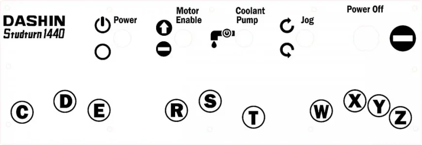
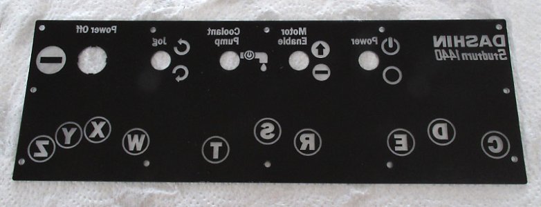
The control panel obviously needs some nice labels. I created the following design in Adobe Illustrator. It is carefully sized to match the new control panel.

I used some acrylic sign making material (https://www.trotec-materials.com/laser-materials/plastic/trolase-reverse.html) and one of the laser cutters at Protospace to make the front of the control panel.
The panel is made out of 1/16" clear acrylic that is painted on one side with paint that provides a brushed aluminum look when looking through the acrylic, and is black on the back. You then use the laser to cut out the panel, and all the required holes, then engrave all the marking you want on the panel. The engraving burns off the paint on the back side and leaves the acrylic sort of a frosted clear where it is engraved. Then using some acrylic paints (I have easy access to that as my wife owns an art supply store), you paint the clear sections from the rear. The rear painting does not have to be accurate in any way since the paint will only be visible where the rear coating has been burnt away.
It easier to show with pictures. We start with the above graphic burn it in reverse on the back side of the acrylic, and cut the appropriate holes. It took the laser cutter about 5 minutes to do this.

Then grab some acrylic paints from my wife's studio and use a small brush and rear-paint it. No skill required:

Once it dries, the front looks like this:

And a close up:

I think it looks great. It is acrylic though, so it is not as durable as a screen printed piece of aluminum. But, since all the paint and graphics are on the rear scratches will not affect the text or colors, and would have to be very deep to really cause a problem.
I used more mounting screws than the original panel had, and put nylon washers under each screw to reduce the chance of the acrylic getting stressed and cracking.
Once I installed it, here is what the new control panel looks like:

And:

The control panel obviously needs some nice labels. I created the following design in Adobe Illustrator. It is carefully sized to match the new control panel.
I used some acrylic sign making material (https://www.trotec-materials.com/laser-materials/plastic/trolase-reverse.html) and one of the laser cutters at Protospace to make the front of the control panel.
The panel is made out of 1/16" clear acrylic that is painted on one side with paint that provides a brushed aluminum look when looking through the acrylic, and is black on the back. You then use the laser to cut out the panel, and all the required holes, then engrave all the marking you want on the panel. The engraving burns off the paint on the back side and leaves the acrylic sort of a frosted clear where it is engraved. Then using some acrylic paints (I have easy access to that as my wife owns an art supply store), you paint the clear sections from the rear. The rear painting does not have to be accurate in any way since the paint will only be visible where the rear coating has been burnt away.
It easier to show with pictures. We start with the above graphic burn it in reverse on the back side of the acrylic, and cut the appropriate holes. It took the laser cutter about 5 minutes to do this.
Then grab some acrylic paints from my wife's studio and use a small brush and rear-paint it. No skill required:
Once it dries, the front looks like this:
And a close up:
I think it looks great. It is acrylic though, so it is not as durable as a screen printed piece of aluminum. But, since all the paint and graphics are on the rear scratches will not affect the text or colors, and would have to be very deep to really cause a problem.
I used more mounting screws than the original panel had, and put nylon washers under each screw to reduce the chance of the acrylic getting stressed and cracking.
Once I installed it, here is what the new control panel looks like:
And:
Attachments

Last edited:
JohnW
(John)
And now onto some electrical stuff.
I obtained an Allen-Bradley PowerFlex VFD used from e-Bay waaaay back when I started this project, and it has always been the plan to use it to drive the 5HP 3-phase motor on this lathe. As with most home shops, my shop power supply is single phase.
This is my installed VFD. The label says PowerFlex "40", but it is a "4", not a "40". I'm not complaining, having the wrong cover plate was the only bad thing about that e-bay purchase - I can live with that. The wires coiled on the back are for a future enhancement that I will describe when I do it.

I mounted it behind the headstock where it would stay clear of most chips and splash that might come from the lathe, but still be reasonably easy to reach, and I can easily see the display that can show things like motor drive frequency, rpm, or current draw, etc. The control knob is what I will be using for speed control. It could easily be moved to somewhere else, but I decided not to.
I welded up a stiff bracket to hold the VFD and allow the various wires to be securely fastened and reasonably well protected. The bracket is held by two 3/8" studs that are threaded into the cast iron of the headstock. My aluminum TIG welding is getter better, but not quite show-quality yet.
The metal box under the headstock at the back is the main junction box and contains the control electrics, which I will be posting about soon. Some day I will make side covers for the bracket just under the VFD to better enclose the power wires.

A side note: I had to buy three new belts for the machine as what I got with it had belts that were unevenly worn. When running the motor slowly I could hear the belts squeaking because they were riding at different heights on the pulley. They are installed here and work much better that the originals.
A bit of background on VFD's for those that might not be as electronically geeky as I am:
When using a VFD, you can use acceleration and deceleration curves to start and stop the motor, which is nice since it keeps down the stresses on the mechanical components and the peak currents that the motor draws. When you accelerate, the VFD (obviously), takes power from the electric supply grid and uses it to apply energy to the motor to speed it up. No problem there.
You can also have the VFD smoothly decelerate the motor rather than waiting for it to coast to a stop, or using a physical brake.
When decelerating, the VFD must take the energy from the motor (and all the other rotating stuff like a big, heavy chuck) and do something with it. On very large VFD's and much more complex systems it can be fed back into the grid. In smaller systems, any excess power is just dumped into what are called braking resistors to make some heat. It is possible to do without braking resistors, but if you try to use the VFD to slow down the motor much faster than it would coast to a stop on its own you will get an error on the VFD since it needs to dump the power somewhere and it can't.
The first thing VFD's do is take in the input AC and rectify it to create what is called a DC bus voltage. That voltage will be in the order of 1.4x (square root of 2) the input voltage on a single phase input, so 240V AC will create a DC bus voltage of about 340V. If the VFD had 3-phase 208 as its input the DC bus voltage would be about 360V (208 * sqrt(3)).
The VFD's then use solid state devices called IGBT's (insulated gate bipolar transistors) - basically big high voltage and high power transistors - to rapidly switch the DC bus to create a 3-phase AC current to run the motor at almost any frequency you want. The internal computer and software uses the various signals and parameters applied to the VFD to create a suitable 3-phase AC current to drive the motor.
When accelerating, or even just running, the DC bus will be re-charged from the line, and stay in the 340V range (from here on, I will consider only a single phase 240V fed VFD).
However, when decelerating quickly, the motor acts as a generator and will feed power back into the DC bus. That will make the DC bus voltage rise. If it rises to around 400V or so, the VFD will protect itself by disconnecting from the motor and indicating a fault condition (DC Bus over-voltage error). Basically it shuts down rather than exploding. After that you must reset the fault to continue. Once the VFD disconnects, the lathe will coast to a stop unless you use a physical brake.
Most VFD's have the ability to use a big resistor to dump the extra energy into to control the DC Bus voltage. As the voltage approaches 400V, it will start to dump energy into the braking resistors. It will then attempt to keep the voltage in the high-300's until the motor is stopped again and not acting as a generator.
That theory was the lead-up to me describing the braking resistor setup I've installed.
Commercial braking resistors can be expensive, but resistors are simple things, so I made up my own.
My VFD is rated to use braking resistors down to 36 ohms. Using a lower resistance risks blowing up the VFD as the resistors will take too much current. I found a good deal on a few 100 ohm, 225W ceramic resistors. Placing them in parallel provides a 50 ohm load to the VFD which will allow the VFD to dump energy but not so much as to hurt itself.
The resistors are rated to 10x that power for up to 10 seconds, so they can each handle peak loads of 2250 watts for a total of 4500 watts. At that power level they can stop the lathe in only a couple of seconds, so even if I were to cycle the lathe from full forward to full reverse several times in a row, I would not exceed the capabilities of the resistors.
Here is what my home made braking resistor setup looks like:

I got the resistors at a clearance price because they are not ROHS certified (there is lead in the solder on them). Nobody can really use them in commercial products. So, $3 each instead of about $30 each. I'm OK with the lead. They are mounted on two raised studs that are attached to a nylon rod that is then attached to the lathe. Good insulation is important here as there is almost 400V on these puppies. They are mounted far enough above the nylon rod that there should be no problem with heat getting back to the rod and causing problems.
The thermal switches JB-Welded on each side are normally closed thermal switches. They will open at about 130C. The thermal switches are wired in series as part of the enable circuit for the VFD (more on that later), so if the resistors get too hot for some reason, the lathe will shut down until they cool again. JB Weld is good for over 260C constant and 316C for up to 10 minutes, so that should be OK.
The resistors are installed in the left pedestal under the headstock where they are well protected from oil and metal chips and should have good ambient cooling.

Mounting them vertically will give the best cooling since they are hollow and hot air can rise on both the inside and outside of the ceramic.
I obtained an Allen-Bradley PowerFlex VFD used from e-Bay waaaay back when I started this project, and it has always been the plan to use it to drive the 5HP 3-phase motor on this lathe. As with most home shops, my shop power supply is single phase.
This is my installed VFD. The label says PowerFlex "40", but it is a "4", not a "40". I'm not complaining, having the wrong cover plate was the only bad thing about that e-bay purchase - I can live with that. The wires coiled on the back are for a future enhancement that I will describe when I do it.
I mounted it behind the headstock where it would stay clear of most chips and splash that might come from the lathe, but still be reasonably easy to reach, and I can easily see the display that can show things like motor drive frequency, rpm, or current draw, etc. The control knob is what I will be using for speed control. It could easily be moved to somewhere else, but I decided not to.
I welded up a stiff bracket to hold the VFD and allow the various wires to be securely fastened and reasonably well protected. The bracket is held by two 3/8" studs that are threaded into the cast iron of the headstock. My aluminum TIG welding is getter better, but not quite show-quality yet.
The metal box under the headstock at the back is the main junction box and contains the control electrics, which I will be posting about soon. Some day I will make side covers for the bracket just under the VFD to better enclose the power wires.
A side note: I had to buy three new belts for the machine as what I got with it had belts that were unevenly worn. When running the motor slowly I could hear the belts squeaking because they were riding at different heights on the pulley. They are installed here and work much better that the originals.
A bit of background on VFD's for those that might not be as electronically geeky as I am:
When using a VFD, you can use acceleration and deceleration curves to start and stop the motor, which is nice since it keeps down the stresses on the mechanical components and the peak currents that the motor draws. When you accelerate, the VFD (obviously), takes power from the electric supply grid and uses it to apply energy to the motor to speed it up. No problem there.
You can also have the VFD smoothly decelerate the motor rather than waiting for it to coast to a stop, or using a physical brake.
When decelerating, the VFD must take the energy from the motor (and all the other rotating stuff like a big, heavy chuck) and do something with it. On very large VFD's and much more complex systems it can be fed back into the grid. In smaller systems, any excess power is just dumped into what are called braking resistors to make some heat. It is possible to do without braking resistors, but if you try to use the VFD to slow down the motor much faster than it would coast to a stop on its own you will get an error on the VFD since it needs to dump the power somewhere and it can't.
The first thing VFD's do is take in the input AC and rectify it to create what is called a DC bus voltage. That voltage will be in the order of 1.4x (square root of 2) the input voltage on a single phase input, so 240V AC will create a DC bus voltage of about 340V. If the VFD had 3-phase 208 as its input the DC bus voltage would be about 360V (208 * sqrt(3)).
The VFD's then use solid state devices called IGBT's (insulated gate bipolar transistors) - basically big high voltage and high power transistors - to rapidly switch the DC bus to create a 3-phase AC current to run the motor at almost any frequency you want. The internal computer and software uses the various signals and parameters applied to the VFD to create a suitable 3-phase AC current to drive the motor.
When accelerating, or even just running, the DC bus will be re-charged from the line, and stay in the 340V range (from here on, I will consider only a single phase 240V fed VFD).
However, when decelerating quickly, the motor acts as a generator and will feed power back into the DC bus. That will make the DC bus voltage rise. If it rises to around 400V or so, the VFD will protect itself by disconnecting from the motor and indicating a fault condition (DC Bus over-voltage error). Basically it shuts down rather than exploding. After that you must reset the fault to continue. Once the VFD disconnects, the lathe will coast to a stop unless you use a physical brake.
Most VFD's have the ability to use a big resistor to dump the extra energy into to control the DC Bus voltage. As the voltage approaches 400V, it will start to dump energy into the braking resistors. It will then attempt to keep the voltage in the high-300's until the motor is stopped again and not acting as a generator.
That theory was the lead-up to me describing the braking resistor setup I've installed.
Commercial braking resistors can be expensive, but resistors are simple things, so I made up my own.
My VFD is rated to use braking resistors down to 36 ohms. Using a lower resistance risks blowing up the VFD as the resistors will take too much current. I found a good deal on a few 100 ohm, 225W ceramic resistors. Placing them in parallel provides a 50 ohm load to the VFD which will allow the VFD to dump energy but not so much as to hurt itself.
The resistors are rated to 10x that power for up to 10 seconds, so they can each handle peak loads of 2250 watts for a total of 4500 watts. At that power level they can stop the lathe in only a couple of seconds, so even if I were to cycle the lathe from full forward to full reverse several times in a row, I would not exceed the capabilities of the resistors.
Here is what my home made braking resistor setup looks like:
I got the resistors at a clearance price because they are not ROHS certified (there is lead in the solder on them). Nobody can really use them in commercial products. So, $3 each instead of about $30 each. I'm OK with the lead. They are mounted on two raised studs that are attached to a nylon rod that is then attached to the lathe. Good insulation is important here as there is almost 400V on these puppies. They are mounted far enough above the nylon rod that there should be no problem with heat getting back to the rod and causing problems.
The thermal switches JB-Welded on each side are normally closed thermal switches. They will open at about 130C. The thermal switches are wired in series as part of the enable circuit for the VFD (more on that later), so if the resistors get too hot for some reason, the lathe will shut down until they cool again. JB Weld is good for over 260C constant and 316C for up to 10 minutes, so that should be OK.
The resistors are installed in the left pedestal under the headstock where they are well protected from oil and metal chips and should have good ambient cooling.
Mounting them vertically will give the best cooling since they are hollow and hot air can rise on both the inside and outside of the ceramic.
Last edited:
JohnW
(John)
Thanks. I thought Colchester's were British made. Am I wrong? I don't really know, I just asking.great read. F.Y.I. Colchester lathes have been made in Taiwan and now China for almost 30 years.
Mine is a clone of a Colchester that is either Taiwan or Chinese from the late 1970's (the motor nameplate indicates 1978 - assuming the original motor). I know that many companies copied much of the design once the original patents ran out.
One big different between this lathe and the Colchester Triumph 2000, which is the closest match I've seen is that the original had a clutching system in the headstock that allowed the motor to run and the spindle to be engaged via a clutch. My lathe does not have that.
In the feeding gearbox, there are also some very minor differences form the official Colchester deign (i.e. something like using 13/26 gears instead of 14/28 gears, still 2:1, but just slightly different). I don't think I have posted about the gearbox yet. I will do that some day.
Last edited:
JohnW
(John)
And one more quick post for tonight:
I have the VFD programmed to run the motor from 6 to 90Hz. The nominal line frequency is 60Hz, and the motor runs at about 1725 RPM with no load at that frequency. Induction motors always run at slightly lower than their nominal RPM in relation to the frequency. At 60Hz the nominal RPM is 1800 for a two pole motor. That is because induction motors only generate torque as they slip in relation to the rotating magnetic field created by the AC current. At 1800 RPM with 60Hz the motor has zero torque, so it slows down as it cannot overcome its own friction at that speed. As it drops below 1800 RPM it starts to develop torque and eventually settles at an RPM just under 1800 RPM where the torque equals the running friction.
I tried to run the motor slower than 6 Hz, but it got quite unhappy at abut 4 Hz, slowing down dramatically and making a high-pitched squealing. That is likely caused by a harmonic of the 16KHz switching frequency used by the VFD to make the AC that is driving the motor. 6Hz seemed like a good low-end frequency to stay away from any motor problems.
The higher the speed you select (beyond the nameplate frequency of 60Hz), the lower the motor torque will be. The VFD can in theory generate up to 240Hz, but the motor would have very little torque at that speed. Also the motor was designed to run up to about 1800 RPM. Going very much faster can be hard on the bearings, depending on how well it is balanced, and the centrifugal forces get larger at higher speeds.
I found some information in the web that indicates that almost all motors of 10HP or less can be run at 2x their nameplate frequency, but I thought I'd play it safe and stick to 1.5x or 90Hz.
That makes the speed range of the motor from about 150rpm up to about 2600 RPM when driven by the VFD.
With lower frequencies (than the nameplate frequency) the motor maintains almost all of its torque and runs very smoothly with even torque. That's great so the little VFD knob can be used to adjust the speed instead of changing a lot of gears.
Except there is a problem: The slower the motor goes, the less cooling it gets from its built-in fan because the fan is turning slower (obvious). However, at lower frequencies, it is still making the same amount of heat. So running it say, 20 Hz under load can easily over heat the motor.
My solution:

This is a 24V 1.5A fan that blasts a huge amount of air. I got it out of an old mainframe computer 20 years ago. The VFD has a small relay built into it that can be programmed to do various things. I've programmed it to run this fan whenever there is power applied to the motor. Inside the control box (more on that later) there is a small 20V laptop power supply that runs this fan. The fan still pushes a huge amount of air at 20V.
The bottom line - even when running the motor slow, it should still have lots of cooling.
I have the VFD programmed to run the motor from 6 to 90Hz. The nominal line frequency is 60Hz, and the motor runs at about 1725 RPM with no load at that frequency. Induction motors always run at slightly lower than their nominal RPM in relation to the frequency. At 60Hz the nominal RPM is 1800 for a two pole motor. That is because induction motors only generate torque as they slip in relation to the rotating magnetic field created by the AC current. At 1800 RPM with 60Hz the motor has zero torque, so it slows down as it cannot overcome its own friction at that speed. As it drops below 1800 RPM it starts to develop torque and eventually settles at an RPM just under 1800 RPM where the torque equals the running friction.
I tried to run the motor slower than 6 Hz, but it got quite unhappy at abut 4 Hz, slowing down dramatically and making a high-pitched squealing. That is likely caused by a harmonic of the 16KHz switching frequency used by the VFD to make the AC that is driving the motor. 6Hz seemed like a good low-end frequency to stay away from any motor problems.
The higher the speed you select (beyond the nameplate frequency of 60Hz), the lower the motor torque will be. The VFD can in theory generate up to 240Hz, but the motor would have very little torque at that speed. Also the motor was designed to run up to about 1800 RPM. Going very much faster can be hard on the bearings, depending on how well it is balanced, and the centrifugal forces get larger at higher speeds.
I found some information in the web that indicates that almost all motors of 10HP or less can be run at 2x their nameplate frequency, but I thought I'd play it safe and stick to 1.5x or 90Hz.
That makes the speed range of the motor from about 150rpm up to about 2600 RPM when driven by the VFD.
With lower frequencies (than the nameplate frequency) the motor maintains almost all of its torque and runs very smoothly with even torque. That's great so the little VFD knob can be used to adjust the speed instead of changing a lot of gears.
Except there is a problem: The slower the motor goes, the less cooling it gets from its built-in fan because the fan is turning slower (obvious). However, at lower frequencies, it is still making the same amount of heat. So running it say, 20 Hz under load can easily over heat the motor.
My solution:
This is a 24V 1.5A fan that blasts a huge amount of air. I got it out of an old mainframe computer 20 years ago. The VFD has a small relay built into it that can be programmed to do various things. I've programmed it to run this fan whenever there is power applied to the motor. Inside the control box (more on that later) there is a small 20V laptop power supply that runs this fan. The fan still pushes a huge amount of air at 20V.
The bottom line - even when running the motor slow, it should still have lots of cooling.
Very nice restoration/upgrade project, you have built a nice machine there!
Regarding those big resistors, that's exactly what I was wondering about when people set up proximity switches on the lathe bed. I've seen a video of single point threading. A switch sensed carriage position & the motor came to an almost abrupt stop. I can visualize the signal could say 'ramp down' maybe over several seconds, but couldn't help but thinking short duration 'braking' must involve dissipating quite a bit of energy. Would you say the resistors would be a common part of any VFD configuration if you wanted this capability or because you have more HP? For example my 14x40 lathe has a 1.5HP motor 220v 1P.
I remember you posted some good info about VFD lathe motor conversion.
https://canadianhobbymetalworkers.com/threads/lathe-power-off-timing.812/#post-7808
Tom Kitta
Ultra Member
Given that the lathe has change gears what is the advantage of a VFD? More fine tuned speed control? Can slow down all they way to 10 rpm if needed at a cost of torque? Can slightly over speed (within bearing limits/ other limits)? Faster stop without having to hit the break (at the cost of having extra resistors installed)?
Your lathe looks like a smaller version of my Indian lathe - maybe if you need more challenging project you can take a look.
Your lathe looks like a smaller version of my Indian lathe - maybe if you need more challenging project you can take a look.
I have a friend that put a VFD on his 18X72 10HP lathe... He added a solenoid to the resistive breaking circuit to also engage his drum brake. He gets very consitent 1 turn stopping in a single revolution at 400 RPM! I just shake my head when I see it work - wow. The benefits of advanced VFD programming and good braking resistors.
JohnW
(John)
Peter:
With braking resistors, the lathe can slow down really fast. It can come to a stop faster than it can accelerate. If it has a 2HP motor (for instance), and it takes 1 second to go from 0 RPM to 1000 RPM on the spindle, it can go from 1000 to 0 in less than 1 second.
That is because when accelerating, it has to fight friction, when decelerating, friction is helping.
The VFD can be told to use whatever acceleration curves you want. For most operations, I have mine set to a 2-second ramp up/down which I think is a reasonable compromise between waiting for speed to change, peak power usage, and wear and tear on mechanical things. When deceleration is triggered by the brake switch on my machine, it switches to a 0.5s ramp down. The bottom line is I will only use the brake lever when I really want it to slow down. In normal stops, the 2s ramp down is fine.
If I have my big 4-jaw chuck on spinning at 2000 RPM, it will need to use the braking resistors to achieve a 2 second stop time.
It does involve dissipating a lot of energy to quickly stop a big rotating thing. That is why the resistors are big. My motor is rated at 14A @ 208V, so that is around 3000W. The motor also can generate about that amount of power when running as a generator, so the resistors need to be able to absorb that sort of power. In my case the resistors are rated at 4500W for up to 10 seconds. in reality, the braking circuit of my VFD is only rated to feed about 10A into the resistors, and in my case with a 50 ohm load, it will only be able to feed about 8A which at 400V is about 3200W. Intermittently, my resistors can handle that easily. Used continuously, my resisters would quickly (< 30 seconds) get dangerously hot. That is why I installed the temperature sensors that will shut down the VFD if the resistors are too hot as a just-in-case.
Another analogy is comparing the brakes on a large aircraft to those on a train. One needs to dissipate a huge amount of energy for 10-20 seconds, but never more than every 20 minutes or so (worst case, it has to abort a take-off 20 minutes after landing). The other needs to be able to dissipate an even larger amount of energy almost continuously when going down a mountain pass. I've installed the aircraft version.
Are the resistors required with a VFD? Not really. Only if you want to be able to electrically slow the machine much faster than it would normally glide to a stop. In my case, I found a good deal on the resistors, and it was a fun project to built them, so it was worth it to do.
There is another way that VFD's can apply braking. It is called DC braking. In that case the VFD applies a DC current to one or more of the field coils which causes a stationary magnetic field (instead of the rotating field that normally drives the motor). In that case the stopping is less controlled, and the heat ends up in the armature and field coils of the motor. The motor is large. As long as you don't do that continuously, the heat will not be an issue. Doing that continuously could be a bad thing.
In resistor loads rated for continuous use (like what might be used to control a down elevator full of people), there is an array of heating elements and fans to be able to continuously dissipate the energy. That is a large and expensive sort of thing - especially in a safety related use like with elevators. In that sort of implementation, usually the DC busses of several VFD's will be connected in parallel, so the power used by the up elevator can be fed by the down elevator. The big dummy loads are still required in the evening when all the elevators might be going down full of people as everybody goes home. At that point, a reverse VFD that takes the excess power in the DC buss and feeds it back into the grid might also be used. the elevators might even be programmed do go down more slowly than usual if there are several moving down at once.
The point is that you have the full power of the motor to decelerate the machine when using a VFD, not just internal friction.
If you have a good physical brake (like one that can absorb 5HP of power), the brake can stop it twice as fast as a 2.5HP motor. The VFD does it with no wear to anything though. Like using your transmission to slow down your car when going down a hill instead of the brakes.
If you want to stop really, really fast, you might need the help of a really good physical brake. Remember though that braking that hard can be hard on the gears since you are snapping it from running under power to reverse very quickly and will likely be taking at least some of the gears across their lash and impacting once the lash has been taken up. If the brake were to be on the spindle it would be a lot easier on the head stock gears.
Tom:
Those are the main advantages.
Yes, change gears give you several speeds. Usually more than enough, but only in steps. The variable speed motor allows you to achieve any speed, or make small speed adjustments very easily. It also gives you a wider range of speeds - probably down to 25% of your slowest gear to 150% of your fastest. So, a machine that had geared speeds from 100 - 1000 RPM could be extended to 25 - 1500 RPM.
Is the variable speed control required in most cases - no. Is it a nice to have - yes.
One case where variable speed can be useful is when facing a large surface. You can start the operation at maybe 20Hz with appropriate gearing to have a good surface speed on the outside of the part. As you work towards the center, you can increase the frequency to the motor. That way you can maintain an acceptable surface speed over maybe 90% of the face, rather than only maybe 25% when facing at a constant RPM.
Another is when machining to a shoulder (like threading that Peter mentioned). With the VFD, you can slow it right down as you get close, and then when you hit the brake at the last moment, it will likely stop in much less than a quarter of a turn.
Slowing down the frequency does not cause a significant reduction in torque at the motor (until you get really slow - the reason I've limited mine to a minimum of 6Hz). When running at 10Hz, for instance, the magnetic fields in the motor still come up to full strength and pulls the armature with the same force. Power is RPM x torque, so there is less power coming out of the motor when running at lower frequencies, but roughly the same amount of torque at the motor.
When you achieve the lower RPM at the spindle with gearing, the gearing increases the spindle torque and you maintain the same power output, but with higher torque at the spindle.
With a VFD it is normal to use both gearing and frequency control. Set the gears to the approximate speed range, and then us the VFD to adjust the speed from there. You can easily change speeds while cutting as you see the results of the cut. In most cases I will probably run my VFD between 45 and 80 Hz.
The torque is much smoother with a 3 phase motor as when compared to a single phase motor. That is probably the biggest advantage of a VFD - the ability to use a 3-phase motor. It is the equivalent of a 2 cylinder engine when compared to a 6 cylinder engine with power strokes spread evenly around the rotation of the crankshaft. The 3-phase motor provides almost constant torque, while a single phase motor must use inertia to glide between times of no torque between its "power strokes". Compare a 2-cylinder Harley (very unevenly spaced power strokes) with a 6 cylinder Goldwing. The difference in smoothness is night and day. Constant speed on a lathe can significantly affect surface finish by keeping a constant chip load..
The bottom line is that I'm an electronics geek in addition to a machining geek, so playing with and learning about VFD's and motor control is also fun for me. Also, the VFD is necessary when you have a 3-phase motor and only single phase service. Once you've been forced to have a VFD, you may as well use all of its features.
Last edited:
JohnW
(John)
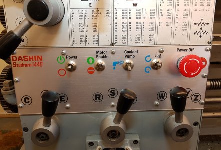
This post is the first of several about the lathe controls in general. Now that I've built it, I'll describe how all the controls work, and then go into how I implemented it all in further posts. I spent a lot of time designing all this, so it might be useful if someone else is considering doing something silly like completely re-wiring a piece of their equipment.
So first there is the main control panel. I've already posted a similar image, but here it is again for reference:

Power:
So first there is the main control panel. I've already posted a similar image, but here it is again for reference:
Power:
- This is a momentary switch with the center position being off.
- Pressing it up engages and latches the main power to the lathe.
- Pressing it down unlatches the main power relay (contactor) and turns the main power off.
- Turning the power off while it is running will cause it to coast to a stop.
- When the power is turned off, the VFD takes about 30 seconds for its capacitors to drain to a level where it displays an input under-voltage fault, and then the display finally goes blank after about 10 more seconds.
- It takes the VFD about 10 seconds to boot itself up when power is turned on. That is one of the reasons for the Motor Enable switch, so the VFD is not continuously cycled, which is not particularly good for it. It is better to cycle it less often.
- Turning off the power also brakes the enable line to the VFD, so the VFD will instantly stop powering the motor.
- It is important to use momentary contacts on the main power so if there is there is a power failure that the lathe will not automatically power itself back on when the power comes back on.
- There is a 120V plug on the back of the machine that provides 120V (limited via an internal 7A breaker) to power external things like the DRO and some extra lighting I will eventually install above the lathe. That plug is live whenever the lathe is powered up.
- A normal on / off switch.
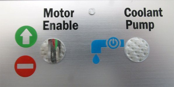
- The VFD has an enable circuit that has several switches in series. This is one of them.
- If you set this to disable, it tells the VFD to not run the motor under any circumstances. Other switches in this circuit are the brake resistor over-temp switches, and an extra contact on the main power relay.
- All of the switches in the enable circuit must be closed in order for Motor Enable to work, so a wiring or switch problem will tend to disable the motor rather than accidently enable it.
- This is useful when working on setups. Like maybe adjusting a 4-jaw chuck. It is not necessary to turn the whole machine off to safely have the motor disabled.
- The auxiliary power plug stays on when the motor is disabled so the lights and DRO remain on.
- Turning this off while the motor is running will cause it to coast to a stop.
- This one's pretty simple. It simply turns the power on and off to the coolant pump.
- I probably could have integrated this with the motor or the enable circuit so the coolant would only be on when the motor is on, but I choose to keep it simple for once.
- Another momentary centre off switch.
- Pressing down gives a forward jog command to the VFD. It runs the VFD at 6Hz with a 0.5sec up and down ramp. It is easy to just rotate the chuck a fraction of a turn with a flick of this switch.
- It has no affect if the motor is in regular forward or reverse motion as commanded by the F/R lever.
- Pressing it up actually runs the motor momentarily in reverse. I had planned this to be just like forward jog with different speeds and ramps, but the VFD won't do it without disabling some other stuff that I think is more important (I would need a fancier VFD with three digital inputs instead of just the two mine has).
- Still, it works OK as reverse jog. A brief flick upwards jogs the lathe backwards without actually going very fast or very far. The lathe is programmed with a 2 second ramp for normal operations, so a 1/4 second flick does not go very far or fast.
- Not called Emergency Stop since what it really does is turn the power off.
- Still a good thing if for some reason it is running (or on fire) and does not want to stop.
- If the lathe is running it will coast to a stop when the power is off.
- It is much faster to stop the machine using the brake lever across the bottom, and the Motor Enable function is better for doing setups, so this is unlikely to be used much.
JohnW
(John)
On to the Forward / Neutral / Reverse Lever:
I may have posted this image before, but over on the bottom right is the FNR lever. The bottom shaft has a keyway running the length of it. The lever has a key that runs in that keyway to rotate the shaft and then move the shaft on the bottom left of this image in and out. When I rebuilt the machine, the key was very loose from wear, so I made a new one. Sorry, no pictures of that.

I put the bracket that holds the FNR level in the mill and re-machined the slots that are used as the detent. They don't look great in this image, but they were way worse before I cleaned it up. The lever was very easy to knock from the neutral to the forward position because the side of the deeper slot was rounded off. The lever has a roll pin that sticks out and sits in the deepest slot for neutral, and is limited by the wider slot for the forward and reverse directions. I ended up drilling it out and installing a larger diameter roll pin and making the slot wider to be able to machine off the worn part.

When the FNR shaft near the headstock moves in and out, it move this HDPE ramp that I made (see a previous post) past two micro switches on the back of the lathe. What I inherited here looked like a poor repair of something that had been broken in the past. It was not good.


When using the FNR lever there a couple of things to note:
I may have posted this image before, but over on the bottom right is the FNR lever. The bottom shaft has a keyway running the length of it. The lever has a key that runs in that keyway to rotate the shaft and then move the shaft on the bottom left of this image in and out. When I rebuilt the machine, the key was very loose from wear, so I made a new one. Sorry, no pictures of that.
I put the bracket that holds the FNR level in the mill and re-machined the slots that are used as the detent. They don't look great in this image, but they were way worse before I cleaned it up. The lever was very easy to knock from the neutral to the forward position because the side of the deeper slot was rounded off. The lever has a roll pin that sticks out and sits in the deepest slot for neutral, and is limited by the wider slot for the forward and reverse directions. I ended up drilling it out and installing a larger diameter roll pin and making the slot wider to be able to machine off the worn part.
When the FNR shaft near the headstock moves in and out, it move this HDPE ramp that I made (see a previous post) past two micro switches on the back of the lathe. What I inherited here looked like a poor repair of something that had been broken in the past. It was not good.
When using the FNR lever there a couple of things to note:
- If the lever is moved from N to F or R the motor turns on in the correct direction based on the contacts that are made by the micro switch (obvious).
- Those wires control an interlock relay in the control box that signals a forward or reverse command to the VFD (more on that later).
- If the motor is turned off for any reason when the lever is in the F or R position, it will not go back on until the lever is returned to the N position and then moved to F or R again. This is the safety interlock.
- The motor could be turned off because the brake lever was pressed. In that case the interlock relay does not allow the motor to restart until the lever is returned to the neutral position. You don't usually want the motor to restart after pressing the brake even though the lever is still in the F position.
- The motor could also be turned off because the motor enable switch was switched off. In this case the VFD is programmed to not restart the motor if it is enabled while a forward or reverse command is present. The lever has to be returned to N first. Again, a safety interlock.
- If the lathe power is turned on with the FNR lever in F or R, both the VFD and the interlock relay will prevent the motor from going on until the lever is returned to the neutral position.
Attachments
JohnW
(John)
The next thing is the brake lever. This is the manual foot brake that runs along the floor under the bed. This is what it looked like after being repaired, painted and installed. The lever is held by a small stub shaft in a bushing on the right side. The left side has an extension shaft that goes through a bushing through the left pedestal where it actuates a vertical rod that actuates the actual brake.

The problem is that the shaft on the left side is held in the pipe of the lever by a couple of pinch bolts. this was never very strong and it looks like several attempts were made over the years to repair it when it came loose. Stomping on the brake lever with your foot puts a lot of force on this.
The rod with yellow paint on it in the background was quite a loose fit in the pipe and several attempts had been made to make pinch bolts and through bolts to hold it into the pipe. All of the fixes eventually failed. You can see some of the remnants of that work on the lower part of the image.
My plan was to drill out the lever a bit to clean it up, then insert the short piece of pipe sitting on the workbench and weld it in place with a bar that could hold larger pinch bolts that would have a half inch of thread to bite into. Here is what I started with:

A little cleaning up of the inside of the lever with a large drill bit, and the short bit of re-enforcing pipe could be hammered into place. I had already run a drill bit through the inside of the pipe to clean it up.

Once it was in, I ground out some of the existing holes so I could securely weld the inserted pipe into place.

Once the pipe was welded in place, I added a 3/8" thick bar on top, and drilled and tapped it for 3/8" (grade 5) bolts. The bolts now have over 1/2" of thread to bite into (the new pipe, the old pipe, and the bar) so they should be pretty strong and can be tightened without danger of stripping.

The ID of the inserted pipe is slightly smaller than the shaft, so I machined it down to be a good fit - a few thou clearance. You can see some of the previous attempts to attach this shaft to the brake lever.

To make sure the shaft does not rotate once the bolts are tightened, I machined two flat spots on the shaft for the bolts to clamp down to. Ha-yoo, some real machining pictures!!!

Close-up. Not really beautiful machining, but it is all hidden anyway.

Then I painted it, assembled it, and you can see the finished brake lever in the first image in this post.
I'll get into the brake electrical stuff in the next post.
The problem is that the shaft on the left side is held in the pipe of the lever by a couple of pinch bolts. this was never very strong and it looks like several attempts were made over the years to repair it when it came loose. Stomping on the brake lever with your foot puts a lot of force on this.
The rod with yellow paint on it in the background was quite a loose fit in the pipe and several attempts had been made to make pinch bolts and through bolts to hold it into the pipe. All of the fixes eventually failed. You can see some of the remnants of that work on the lower part of the image.
My plan was to drill out the lever a bit to clean it up, then insert the short piece of pipe sitting on the workbench and weld it in place with a bar that could hold larger pinch bolts that would have a half inch of thread to bite into. Here is what I started with:
A little cleaning up of the inside of the lever with a large drill bit, and the short bit of re-enforcing pipe could be hammered into place. I had already run a drill bit through the inside of the pipe to clean it up.
Once it was in, I ground out some of the existing holes so I could securely weld the inserted pipe into place.
Once the pipe was welded in place, I added a 3/8" thick bar on top, and drilled and tapped it for 3/8" (grade 5) bolts. The bolts now have over 1/2" of thread to bite into (the new pipe, the old pipe, and the bar) so they should be pretty strong and can be tightened without danger of stripping.
The ID of the inserted pipe is slightly smaller than the shaft, so I machined it down to be a good fit - a few thou clearance. You can see some of the previous attempts to attach this shaft to the brake lever.
To make sure the shaft does not rotate once the bolts are tightened, I machined two flat spots on the shaft for the bolts to clamp down to. Ha-yoo, some real machining pictures!!!
Close-up. Not really beautiful machining, but it is all hidden anyway.
Then I painted it, assembled it, and you can see the finished brake lever in the first image in this post.
I'll get into the brake electrical stuff in the next post.
Last edited: