• Spring 2024 meetup in Calgary - tentative date Saturday, April 20/2024. Other regions are also discussing meet ups. If you want one in your area get going on organizing it! discussion
  • We are having email/registration problems again. Diagnosis is underway. New users sorry if you are having trouble getting registered. We are exploring different options to get registered. Contact the forum via another member or on facebook if you're stuck. Update -> we think it is fixed. Let us know if not.
  • Spring meet up in Ontario, April 6/2024. NEW LOCATION See Post #31 Discussion NEW LOCATION

My "New" Lathe

JohnW

(John)
Here is another minor issue and the fix my lathe got a couple of weeks ago:

Vice T-Nuts_3739.jpg
The curved t-nuts that hold the vice to the cross slide were both cracked and a bit bent from over-tightening over the years. Here are the old nuts on top of a piece of hot rolled scrap that has already been through the mill to square it up and remove the scale.

Vice T-Nuts_3740.jpg

I drilled and threaded the two holes first, then bolted it from the bottom with countersunk heads into to a sacrificial piece of MDF that I bolted to my rotary table at exactly the radius of the circular vice hold down slots in the cross slide. This lathe has a strange mixture of metric and SAE fasteners. The vice t-nuts are 3/8-16. There are lots of 1/4-20's holding on access panels yet most of the other bolts are 5mm, 6mm and 8mm.

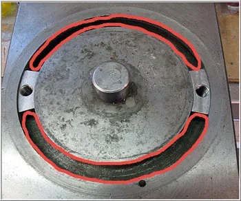
Once I had it carefully mounted in position it was just a matter of taking a bunch of small passes with an end-mill while rotating the table to hew out one large curved t-nut. I had a lot of vibration from the MDF flexing. I should have used 3/4" instead of 1/2", but that is what I had lying around. Still, it worked OK by keeping the cutting passes less than about 0.020" of Z motion.

This time I remembered to grab the camera in the middle of the machining operation. This is when the narrow part of the nuts have been cut. I then moved the table in the X direction and cut the curves for the shoulders of the nuts. Since it was mounted on MDF, I just cut right into the MDF to finish the sides.

Vice T-Nuts_3743.jpg

I cut the piece in half and got two nicely fitting curved t-nuts. The nuts sit about 0.020" below the surface when they are pulled up so they will allow the vice to be clamped down nicely. They are a bit longer than the originals, and are as long as they can be and still fit through the slot in the bottom that they must be inserted through.

Vice T-Nuts_3752.jpg

Here is a comparison of the old and new parts:

Vice T-Nuts_3751.jpg
The originals used bolts that threaded into the t-nuts. I think that contributed to the failure since it eventually wore out the threads, and forced the bolt to hold in the top, very thin portion of the nut.

Instead, I made a couple of studs out of two grade five 3/8" bolts with rolled threads. I have lots of 3/8" ready rod around, but I do not think they are made of very strong metal. I had to extend the threads on the bolts a bit to make the studs - you can see where that started since the bolt is a little bit small right at the end of the rolled threads and leaves a short bit of missing thread on the stud.

I put the studs into the t-nuts and glued them in place with JB weld while keeping a bit of tension on the studs so they would be metal-to-metal while under tension. That way the rolled threads are sticking up and will see the stress and wear instead of my cut threads, the studs won't loosen, and the JB will add some strength to help stop the nuts from splitting like the previous ones. There is still very little metal on each side the threaded holes near the top.

The chamfered edges of the t-nut shoulders was not intentional. That was just the edge of the original metal. The new nuts still have a longer shoulder than the originals.

I had a couple of nice 3/8" shoulder nuts from a small hold-down kit I have for my rotary table. I'll e-bay some replacements out of China some day, but this was a better use for them for now. The nuts were just a bit too tall to fit properly on the vice, so I did two things there. I milled down the nuts a bit, and I took a 1" end mill and cleaned up the mounting surface on the vice by cutting out 0.040" or so. The vice mounting flange was a bit beat up at the edges of the holes by the small surface area of the original hex head mounting bolts.

The other reason I went with the studs is that I prefer to be able to use a wrench to tighten the vice over using an Allen key. With a nice polished surface on the bottom side of the nuts, and a large smooth surface on the vice mounting flanges, the vice can now be tightened very smoothly without moving while the nuts are turned.

And the final result:
Vice T-Nuts_3761.jpg
 
Last edited:

PeterT

Ultra Member
Premium Member
Its always good to use a 3 foot snipe to really crank down that compound I always say :) When I DRO-d my lathe, I also put an encoder on the RHS of compound mine is crowded in there. I ended up having to use cap screws for that reason. My T-slot has a hole on the underside to load the T-nuts in from the underside. I don't quite see how the wider part of your nuts got in there, the threaded boss looks to be the same width as the groove on the base. What am I missing there?

I also put in 2 filler crescent shaped inserts between my T-nuts so they always stay phased at 180-deg if I removed the compound, but this is more to deal my setup being a little more blind finding the nut holes again.
 

Attachments

  • 5-15-2016 0002.jpg
    5-15-2016 0002.jpg
    42.8 KB · Views: 5

JohnW

(John)
With the studs sticking out it is easy to move the t-nuts and position the vice onto the studs, so the spacers are not really required in my case. They are a cool idea though.

My curved t-nuts go in from the bottom via a slot that you can't really see in the previous photos.

Vice T-Nuts_3745.jpg

In this image I was test fitting the nut by inserting it upside down before I cut it up. You can see the opening the t-nuts have to come up through from the bottom in the upper left portion of the slot. I made the new t-nuts as long as I could and still fit though that hole. I don't think it really matters anyway since most of the clamping force will be very close to the stud. I think the longer nut may slide a little more smoothly in the slot.

My lathe DRO is only two-channel, so I will still have to watch the dial and count turns on the compound.
 
Last edited:

Tom Kitta

Ultra Member
Quick question about VFD - how does the 5hp VFD work on your lathe - have you tried it yet? I know there is a lot of talk about "some" VFDs having issues with single phase input as they are using 4 out of 6 inputs & there is some talk about de-rating VFDs.... not sure whatever this deals with people simply wanting bigger.

Other thread talks about 3hp VFD being able to start 50hp motor over 20-30 seconds...

With a lathe it seems the startup is critical as the chuck is heavy - not so with a mill.

Yet other people talk about how it is not possible to run multiple motors on a VFD - while other people compute the VFD power needed just to do that.

Great work on the lathe BTW - I see how much I have to do to restore my old K&T 2E - she is older than my dad. So far the mill head and gears were in as new condition.
 

JohnW

(John)
Sorry, not a big update today, as I'm out of town and just wasting some time in a hotel room.

Most of the ball-oilers (oil nipples) on my lathe were either missing, badly damaged, or just plain gummed up. I don't really have any good pictures pictures of the old ones, but here is what I did.

The machine uses 6mm, 1/4" and 8mm oilers. I looked through e-bay and the usual sorts of suppliers and they are available, but for $5 to $6 EACH plus shipping!. I found one guy on e-bay (out of China), who was selling sets of twenty 6mm and 8mm oilers for less than $5 Canadian (including shipping). He didn't have any 1/4" ones listed though.

Wait a few weeks and here is a picture of a few of the 6mm ones that showed up in the mail. The 8mm ones looked similar. They are very nice little units for super cheap.
Ball Oilers _6mm.jpg

So, what to do about the 1/4" ones I needed?

I found some thin 6mm OD brass tubing in my collection that could shim them up, so I built a swaging tool to expand the 6mm OD tubing to just less than 6mm ID.

First, I cut the tubing into a few 7mm long pieces.
Then, I tapped the long part of the tapered swaging tool into it using the smallest hole in the die portion (#1).
Then continue with hole #2 which is a little bit bigger.
Then finally with hole #3 the taper would go right through and the ID was just under 6mm with the OD just over 1/4".
Ball Oiler - Swaging Tool.jpg
The reason for the different sized holes is that they needed to press against the edge of the tubing so I could press the tapered swaging tool through. With too big of a hole, the tubing would just slide into the hole.

Then I pressed a 6mm oilers into the little piece of tubing. The final hole in the die is tapered, so it rivited the brass tubing over the end of the 6mm oiler so it still has a tapered end to make it easy to tap into the 1/4" oiler holes.

Here is what the modified oilers looked like:
Ball Oiler - .25 Inch from 6mm.jpg
And here is what the oil holes look like with the nice shiny new oil nipples in place.
Ball Oilers - Installed.jpg
Unless you look really closely, you can't even see the sleeves on the 1/4" oilers.

So, for a $10 investment I have nice new oil nipples and a small bag of extras for another project.
 
Last edited:

Johnwa

Ultra Member
Nice work! I searched aliexpress for oil nipples and it came up with a bunch of scantily clad females. I was a little apprehensive searching for ball oilers, but that one worked.
 

JohnW

(John)
I guess I should have posted this information before:

If anybody else is looking for these, the e-bay seller I used was: wenyuandin
He described them as: LOT 20 Brass Push Button oiler press fit ball oiler for Hit&Miss Engine Motor

s-l1600.jpg


Disclosure: I have no connection to the seller other than have made one purchase that I am very satisfied with.
 
Last edited:

Bofobo

M,Mizera(BOFOBO)
Its easy to post lots of stuff when I'm catching up on a project I've been working on for the last few months. . . .so here is another:

I took lid off the headstock to inspect in there after I'd drained the oil. Here is what it looks like:

View attachment 725

Full disclosure: This picture was actually taken after it was all put back together, but I didn't have a good image from when I was taking it apart.

It all looked pretty nice in there. There was just a bit of dirt and some very small debris that had settled to the bottom of the oil.

Once I started checking out all the gears, I discovered that one of the gears on the input shaft was spinning on the shaft. All of the gears on the input shaft are locked into place with a long key - or at least they should be. In the picture above, the input shaft is connected to the triple pulley (the brake is inside that pulley). The rest of the shaft and its gears are sort of visible under the secondary shaft at the bottom of the picture.

Power goes from the input shaft up to the secondary shaft when one of the four gear sets is engaged (four main spindle speeds), and then over to the spindle shaft via the two sets of gears at the left side of the spindle (spindle high-low range). These gears are shifted via the concentric levers on the front panel (there is a picture of that way back near the beginning).

At that point the pulley and brake had already been removed, so with the removal of a few snap rings, the input shaft should have pulled out reasonably easily. Well, it didn't. I had to weld up a custom puller to pull the input shaft off of the input gears and out of the right side of the case. Every millimeter had to be pulled, with me changing sets of washers and spacers on my homemade puller thingie every couple of inches.

Here is what I found:

View attachment 726

At some point in its life, the spindle must have had a serious crash. It sheared the keyway in half, leaving half of the keyway in the slot in the gear, and the rest in the shaft. After that, the gear could spin relatively freely on the shaft.

In the end, this looks much worse than it was. The shaft is scored up a bit under the one gear, but once I filed and polished the high spots back down, the gears still fit it very nicely. The gear that spun, was obviously hardened as it only had some very minor marks on the inside of its centre hole. A bit of grinding compound on a slightly under sized bit of steel I machined up cleaned that right up. Since the gears are fixed to the shaft I didn't think the shaft would need to be replaced.

Since the keyway slot was widened out, I put the shaft on my mill and extended the slot all the way to the end of the shaft. That gave the gear that spun a nice clean slot to hold the keyway a bit better. I bought a new 6mm keyway, then cut it to size to replace the whole key. It was way too tight, so I needed to spend a few hours polishing down the keyway by about 0.03mm to get a good fit.

Unfortunately I didn't take a picture of the repaired shaft, but it went together reasonably smoothly (I used a new oil seal to keep the oil off the brake shoes), and the input shaft was fixed.

Overall, a pretty easy and cheap fix ($10 for the keyway, $2.50 for the seal, and several hours of work) for what could have been a really serious problem.

While I was in there, I carefully inspected all the teeth on all the gears and everything was fine. I also documented all the gear ratios for future reference, including the high-low and reversing gears for the feed drive output shaft.

Here is what the headstock looked like with the input shaft and one of the shifter shafts removed:

View attachment 727

That all went back together nicely. I looked up what oils was required, and it seems that hydraulic oil is a pretty standard lubricant for lathe headstocks, so I added the 8 liters or so that it took to fill it and bolted the lid back on. Actually that's a lie since I didn't really bolt the lid back on until I had finished cleaning and painting everything, but that comes later in the chronology.

Since it made a big mess when I originally drained the oil, I replaced the original threaded oil plug with a short pipe nipple and a cap, so it is possible to drain the oil into a funnel and catch it before it runs all over everything. Hopefully I will never need to drain the headstock again, but it will be easier in the future if I have to.
I recently experienced a sheared woodruff key in my latest dirtbike acquisition. It was all my own fault for not putting enough torque on the bolt, it began to come loose but would still run untill the key sheared in two :( oops but some slight grinding to fit a new one has yielded great results. No tow this muddy weekend! Lol

Keep this one coming it's looking great!
 

JohnW

(John)
Time to catch up on some stuff I did a few months ago - the chip tray and some of the painting.

The original chip tray was a huge drawer that hung under the lathe bed. The best picture I have is one I posted before from when I first saw the lathe before I bought it. The tray is sitting partially pulled out in this image.

Dashin As Found_3342.jpg

The tray is probably great if you are doing lots of cutting all day long. It will hold a day's cuttings and let the coolant drain back into the reservoir for re-use. The whole tray then slides out to make it easy to empty. The tray actually sat a little bit crooked as some angle iron had been welded in to give it some additional slope and it did not really slide in and out very well.

I want to build and install some large drawers under the lathe to store big heavy stuff like the chucks, and did not like the way the drawer worked. Storage space is always at a premium in any shop smaller than a large Walmart store, so I don't like wasting the space under the lathe.

I cut out the front and part of the bottom of the the drawer with my plasma cutter, straightened it and welded it in place with the rest of the sheet metal that sits under the lathe to make up a smaller, flatter tray. I still kept some slope that goes to a drain pipe that feeds into the right hand stand where a future coolant pump may go.

Here is the bottom of the new welded together chip tray:

Chip Tray_3612.jpg
The back of it is facing the camera. I overlapped the metal for a couple of inches and tacked it every inch or so on the bottom. The top was a continuous weld. It slopes to the welded area from the front and the back, and also slopes towards the tube that sticks out on the right side in this picture. That tube goes into a hole I made in the side of the right hand stand, where I will mount the coolant tank and pump if I install one some day. In the meantime, I will just put on a short piece of hose that can drain any cutting oil that runs onto the tray into a small container.

The shiny parts are where I ground the paint off for welding and where it came off because I was pounding on it to straighten out the original bend.

Here it is from the top:

Chip Tray_3623.jpg

I used some body filler to fill in some of the dents and cracks from the original pan (and pretty up a few bits of my ugly welding). The original lathe had body filler all over the place to smooth it out over rough welds and castings. A lot of that came off during pressure washing and especially when I was hammering on the chip pan. Once I sanded the filler, it didn't look nearly as beat up any more.

Chip Tray_3631.jpg
And with some paint it actually looks like it was was meant to be like this. You can see the drain hole on the far side of the lower part of the chip tray. Although the paint looks like it has a lot of brush strokes (it was still wet when i took this picture), as it fully dried and hardened up over a couple of weeks the finish came out looking pretty good. You can see the back-splash and other metal covers leaning against the wall in the background. They haven't been painted yet.
 

JohnW

(John)
Another quick post to catch up on some old and new images of the general assembly and painting. . . .

The paint was not in too bad shape when I got the lathe, but by the time I hit it with degreaser and used the pressure washer on it, a lot of paint and filler flaked off, so it really needed to be painted. The insides were only ever painted with a flat primer that was really hard to clean.

Bases_3613.jpg
These are the base castings after cleaning just before they got painted.

Stripped Lathe_3625.jpg
This is the stripped down lathe after some painting.

Lathe Painted_3637.jpg
I panted the bases (inside and out) and re-assembled the main lathe components. This is still being done under the ceiling hoist I have in my shop.

I used my plasma cutter to cut a new door into the front of the right hand base unit before painting it. It is made of 3/8" steel (not cast). It had an opening on the back, but that would be nearly impossible to get to once the lathe is against the wall. Eventually there will probably be a coolant tank and pump in there. I also welded in a couple of pieces of angle iron to support a base shelf inside the right hand base unit.

I then raised the main assembly onto a heavy duty axle I have (1.5" steel bar with a bearing on each end - visible in this picture) and a heavy duty moving dolly type of platform I have and rolled it over to the other side of the shop and positioned it about 3 feet in front of the wall where it will reside and used a crow bar to let it down onto a couple of 2x4's.

You can also see the 40A 220V stove plug that will power the new beast, and my mill in the background.

Once it is fully assembled (and heavy), I only have to move it back a couple of feet and put it on proper supports.

Misc Painted Stuff_36xx.jpg

I painted lots of other parts before assembling them.

Cracked Backspash_3790.jpg

One corner of the back-splash was cracked, so a bit of MIG welding, grinding and painting fixed that up:

Backspash_Repaired_3793.jpg

And the back-splash with a fresh coat of paint on it with the now more assembled lathe in the background.
Painting Backspash_3791.jpg
 

JohnW

(John)
A couple of days ago, I worked on making new rubber "shoes" for the lathe. The lathe has six adjustable levelling screws on the bottom of the bases - four under the headstock, and two under the tail stock section. The bolts have rounded ends, but I think they would put too much of a point load on my shop floor, likely damaging the surface when I turned them to level the lathe. My solution was to make 3" round hard rubber shoes with a steel top so the lathe could still be easily levelled, but still spread the load a bit and provide a bit of vibration damping.

My solution was to use modified hockey pucks. Hockey pucks are cheap, 3" in diameter, and just about the right material for this.

I started off by plasma cutting some 2 1/2 inch disks from some scrap 1/4" steel plate I had. I got all six out of one piece of scrap with almost no waste. I created a 3" diameter template out of a piece of 1/4" acrylic I had by cutting it out on my old lathe. I was a bit aggressive in cutting out the hole and chipped the acrylic a bit, but it still worked fine as a template. It got slightly melted in a couple of spots during the cutting by some wayward plasma, but it held up for the job, and could still do a bunch more if I needed them. I made sure to remove the acrylic as soon as I was finished cutting so it would not get over heated by the metal.

Rubber Feet_3912.jpg
Here is the acrylic guide clamped to the scrap (it had already had a few disks cut out). The plasma cutter cuts about 1/4" inside of the guide disk, so even in this case I ended up with a nice round disk. When you are cutting something like this, make sure to cut off the little corner bits first so the whole piece doesn't drop out with the corner you were about to cut still attached and then you have to try to re-align the template to cut off the last bit. How do I know that?

Rubber Feet_3921.jpg
Here is me doing the plasma cutting.

Rubber Feet_3931.jpg
I did a quick grind along the edges of the disks to clean up the dross from the plasma cuts, and then put them on the lathe with a 3/4" ball nose end mill in the tail stock to make some dimples for the lathe levelling bolts to fit in.

Rubber Feet_3933.jpg
I put the hockey pucks into the lathe and cut out a relief for the steel plates using an HSS bit. The pucks were really hard on the bit! On the third puck I could smell some rubber burning and the HSS bit was completely dull. The edge had been rounded over and made all shiny by the rubber. After that, I re-sharpened it after every two pucks since it would quickly get dull again.

Rubber Feet_20160530_155553.jpg
I was aggressive in the cutting and ended up with a big pile of rubber spaghetti, so I was not doing lots of rubbing with the bit. Maybe hockey pucks use silica sand as a filler or something? I never thought the rubber would be so hard on an HSS bit. The huge rats nests of rubber made it hard to see what I was cutting.

Rubber Feet_3935.jpg
I put a dab of silicone seal on the pucks and inserted the steel disk. A squish in the vice spread the silicone enough to come out a bit around the edges.

Rubber Feet_20160530_155705.jpg
I've left them sitting in a clamp so the silicone can set. I'll probably leave them there until I'm ready to move the lathe into position and onto its new shiny black shoes. It will probably take a while to cure since it does not get a lot of air under the disk.

A quick update: I mentioned that two of my set of 8 M2 gear cutters got lost in the mail. The Chinese e-bay seller was a good guy and he re-shipped the two missing cutters. They arrived a couple of days ago so it all worked out. You gotta be patient when dealing across the Pacific.
 
Last edited:
L

Louis Dusablon

Guest
I had those under my 14x40 found them a bit bouncy, made some steel ones with a stick on sandpaper underneath worked great.
 

JohnW

(John)
Hmmm, I'll have to see how they work. If they are a problem, I'll just rip off the pucks and go with the steel disks. It will still be a few weeks until I know.

I like the idea of adding on the stick on sandpaper to the metal though.
 

Tom Kitta

Ultra Member
Some great ideas!

I also have few oilers I need for my old mill - good find! The hockey puck gave me an idea! Way cheaper then buying commercial stuff - I guess I am going to buy a lot of stuff at sports store for "alternative" uses.
 
L

Louis Dusablon

Guest
No punt intended here
I do have pucks under my mill also
 
L

Louis Dusablon

Guest
they will be replaced either with steel or aluminum disk
just my thought.
 

JohnW

(John)
I haven't posted an update in a while. Back when the weather was good, I was off riding the motorcycle a lot.

This is another catch-up post showing some work I did earlier this spring.

One of the sub-projects I worked on along the way was the switches driven by the carriage mounted fwd-off-rev level. The lever turns the lowest shaft long the front of the bed, which then moves a rod in and out that goes to the back side of the lathe (lower left in the image below).

The shaft has a keyway along its length, that is engaged by a key in the collar that the fwd-off-rev lever attaches to (a pretty standard configuration). The key was half worn through, so I machined a new key. Sorry no pictures of that. I also squared up the notch that creates the "off" detent position. You can just barely see the notch in the image below.

Carriage and Shafts_3779.jpg

The rod had a couple of hokey levers with a small ramp brazed onto a bolt that actuated two micro-switches as the rod was moved in and out. When I got the machine the tops of the micro-switches were covered with a fine metal-oil mixture, which is interesting since the screw connectors the top of the micro-switches were switching 120V to drive the main motor relays (aka contactors). That was a fire just waiting to happen.

Here is the rod along with the original switch actuator ramps and the new one I machined out of a block of HDPE.

Fwd-Rev_3710.jpg

Here it is installed with the original (cleaned) micro-switches. I had some nice flexible shielded 8 conductor cable, so I connected up all the contacts. The cable will run back to the electrics box where I can connect up the appropriate contacts and run them back into the VFD. These wires will only be carrying low-current 10V signals.

Fwd-Rev_3717.jpg

The two ramps slope in opposite directions. It is shown in the off position here. The rod moves in to turn on one switch, and out to turn the other one on.

Fwd-Rev_3719.jpg

And since some metal filing apparently manage to get down there - it is behind the back splash and reasonably well protected - I installed a plastic cover over it (the bottom of a one litre Castrol oil bottle). Having a shaving fall across a switch contact and turning the motor on unexpectedly would be a BAD thing.

Fwd-Rev_3732.jpg

The next topic will be the installation of the DRO, which I started a few weeks ago, I'm going to finish it this evening, since all I have left to do is mount the display unit.
 

JohnW

(John)
I just came in from the workshop after finishing the DRO install on the lathe.

Here is what it looked like today. It's getting close!

Dashin_Status July 2016_5029.jpg

As usual, the story starts a while ago (early May) ago when I started on the DRO install. I bought DRO's for both my lathe and mill about four years ago. I never got around to installing it on the lathe, which turned out to be a good thing so I didn't have to move it over to this machine. Procrastination can be good sometimes.

They are from Shooting Star Technologies (http://www.star-techno.com/), based in BC near Chilliwack. That was nice since the Canadian dollar was low back then so buying a Canadian product made sense. I've been quite happy with the 3-axis unit on my mill. They use a 1/4" steel rod with a precision gear rack machined into it, and a rotary encoder that slides along the shaft.

So here are some pictures of my install. I made up all the aluminium bits you see, including placing all the encoders and rods underneath 1" x 2" x 1/8" aluminium angle's to protect them. The big aluminium bracket holds both encoders and is bolted to the rear of the carriage. The two "unused" bolts are there to bolt on the taper attachment, which will fit with the DRO brackets installed.

DRO Underneath_3809.jpg

If you look really carefully at the lower front of the tailstock (below), you can see a small notch I filed into the angled portion of it. That notch will cleanly hit the aluminium angle protecting the Y-Axis DRO sensor, so when the tailstock hits the carriage no damage should be done. It would still be a bad thing to power feed the carriage into the locked down tailstock!

DRO_Top_3800.jpg

The notch in the Y-axis cover (below) is there so I can reach the oiling holes for the ways.

I haven't mounted the DRO display yet - just testing it here..

DRO_X-Axis and Display_3805.jpg

I was pondering how to run the wires from the encoders to the display without having them catch on stuff. Luckily, I was going away on two one week trips to Oregon shortly after this (one by car for business, the other by motorcycle to wear out the sides of my tires). That left time for an e-bay order of some drag chain to arrive from China. I found some for about $6 per meter, so I ordered it and went away while the slow boats crossed the Pacific.

I got it a couple of weeks ago, and installed it last week. While I was at it, I installed a vinyl hose so I can easily run coolant up to the moving carriage in the future. It is easy to install now before installing the chain, and before the back splash is installed.

DRO_With Dragchain_4994.jpg

That just left the display to install. I wasn't really sure where I wanted it, so I made up a swinging bracket that allows the display to move anywhere in an arc about a foot in radius. The wires run through some split loom to protect them. There is a short piece of 12ga solid copper wire in the loom near the right hand side in this image that makes it stand up so the bracket can move without stressing the wire.

The bolts at the swivel points are threaded into the lower brackets and have lock nuts on the bottom. That allowed me to adjust the joints to be just a little bit stiff so it will stay where I move it to. They can easily be readjusted in the future if it loosens up.

DRO_Bracket_5021.jpg

Here is what the finished install looks like. The display looks fuzzy because it still has the protective plastic on it.

DRO and Carriage_5029.jpg

I've started working on the wiring, and I will probably work on installing the VFD and the various wiring next.
 
Last edited:
Top