• Spring 2024 meetup in Calgary - tentative date Saturday, April 20/2024. Other regions are also discussing meet ups. If you want one in your area get going on organizing it! discussion
  • We are having email/registration problems again. Diagnosis is underway. New users sorry if you are having trouble getting registered. We are exploring different options to get registered. Contact the forum via another member or on facebook if you're stuck. Update -> we think it is fixed. Let us know if not.
  • Spring meet up in Ontario, April 6/2024. NEW LOCATION See Post #31 Discussion NEW LOCATION

My "New" Lathe

JohnW

(John)
I posted the beginning of this story a couple of weeks, ago, but the posting disappeared, so I'll try it again.

The project started a few months ago, so I'll start with a few postings of history before I get into more recent work I've been doing. I have been taking a bunch of pictures along the way, so there will be pictures.

Back in December we were looking for a metal lathe for Protospace. where I am a member. We came across someone who was selling a bunch of gear and long story short, he had a 16x60 sized lathe (7.5HP), a large Bridgeport clone type of mill (5HP, 48" wide table with a power feed) a smaller 14x40 sized lathe (a 5HP Colchester clone), and a big metal band-saw for sale. He had purchased the gear from an auction several years ago and it spend the time in one of his heated garages having never been used.

He was keen to sell it all for a good price, and Protospace was looking for the lathe and a manual mill. We found someone who wanted the big metal band-saw, and I was kind of interested in upgrading my current lathe (a 12x36 2HP unit from House of Tools about 10 years ago).

So we made the deal and headed out with a picker truck for the Protospace gear, and I took my Jeep and one of my trailers to bring home my new toy.

Dashin on Crane_2015-12-22 15.45.02.jpg
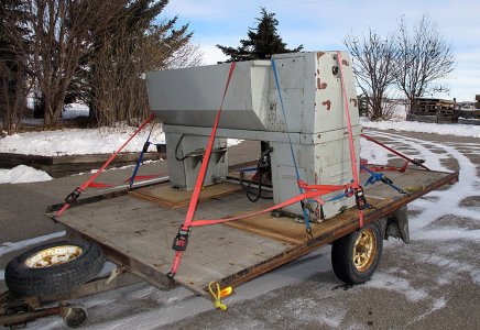
So here we are about 15km east of the city back in December. My new toy is connected to the crane and he is about to put it onto my trailer where I am standing arranging some pieces of scrap plywood to place it on. My trailer can handle the weight as long as it is not too much of a point load. It was probably about 3,000lbs once I removed the chuck, cross-slide vice and tailstock. I originally built the trailer as a snowmobile trailer with a relatively light weight deck, so a bit of re-enforcement seemed like a good idea. The trailer has brakes and a relatively heavy axle and springs since I like the idea of having brakes when hauling stuff on BC highways in the winter.

The other lathe that went to Protospace is sitting there beside my unit. It was loaded onto the truck along with the mill (not visible here), and the big band-saw.
 

JohnW

(John)
It was pretty late and dark by the time I got home. As you can see in the last picture the sun was almost setting while we were loading it up. We first had to unload the other equipment at Protospace in the NE, and I live a few km SW of the City, so I just parked it on the driveway when I got home.

Here is what I found waiting for me on the driveway in the morning:

Dashin_3379.jpg

and from the other end. . . .

Dashin_3381.jpg

The pallet jack was just along for the ride as we were using it move the other gear around at Protospace.
 

Attachments

  • Dashin_3379.jpg
    Dashin_3379.jpg
    437.3 KB · Views: 7

JohnW

(John)
Here's a closer look at the control panel:

Dashin_3382.jpg

The machine is a made in Taiwan clone of the English Colchester Triumph lathe. As near as I can tell it was made in about 1978 (that is the date on the motor label). It has a 5HP 3-phase 208V motor, and appeared to be in pretty good shape. It was well used and there were lots of chips sitting in semi-congealed oil under the gear boxes and all over the motor, so it was going to need some cleaning for sure.

I did find a few issues along the way, and the postings to follow will show the issues and what I did to fix them.
 
Last edited:

JohnW

(John)
The first task was to get this beast off of the trailer. Getting it on was easy; the picker truck did that. I did have a plan to get it off though.

I live on an acreage a few km SW of Calgary that we moved into a few years ago. It included a nice heated shop (3 1/2-ish car garage sized) that I was really looking forward to. The shop only has an 8 foot ceiling, and had a wall down the middle since the previous owner only heated half of it. I had plans for that. I removed the dividing wall and finished and insulated the unfinished half. As part of that project I wanted to have a hoist in the ceiling.

Before I covered in the ceiling, I beefed up a couple of the roof trusses and framed in a big "slot" in the ceiling where I installed an I-beam with a dolly and chain block. The most I had lifted on this since I installed it was my motorcycle. It is much easier to work on when it is lifted up and in no danger of falling over. But that was in the 600lb range, so it was a no brainer. The lathe is 3000lbs-ish so it will be the first real test.

That hoist was how I was going to get the new lathe off the trailer. I backed the trailer in, and hooked the lathe up to the 2-ton chain hoist I had.

Lifting the lathe would be the real test of my engineering. I connected it up and lifted it an inch off the trailer. The roof trusses didn't make any creaking sounds or come crashing down on me, so I guess my re-enforced trusses were up to the task. Even a bit of bouncing on the lathe didn't bring everything crashing down, so I drove the trailer out and carefully let the lathe down to the ground.

Here is the lathe just before I started to let it down.

Dashin_20151223_155018.jpg

There is a 6" I-beam and a chain block in the slot in the ceiling. It didn't fall and crush me, so I was ready to start really checking out the new machine.
 
Last edited:

JohnW

(John)
I'll just make one more quick historical post before I move on to the restoration of the machine.

This is what the machine looked like when I first saw it. Actually this was after about 10 minutes of moving piles of stuff and boxes that were stored in front of and on top of it. There are still a couple of tires there that weren't moved until much later.

Dashin As Found_3342.jpg

As you can see it has a taper attachment. Actually not all of the attachment was there, but the most important part was: the taper slides. I will need to make a bracket to attach the cross slide to the taper attachment and a clamp to clamp the stationary portion to fit to the ways if I ever want to use it. Those are relatively easy to make, and I will probably do so some day.

The chuck is an 8" Bison 3-jaw that is in very nice shape with removable jaws. It seems to be in way too nice a condition to be the original chuck. There were two sets of slightly customized soft jaws for the chuck that will probably come in useful some day. The chuck mount is a D1-5, (it uses six 3/4" pins) which is pretty standard, but not really very common.

It didn't come with a 4-jaw chuck. It has a 40 position tool post, but no tool holders. There is some plumbing and wiring for a coolant system, and a coolant reservoir in the right hand base unit, but there was no coolant pump installed.

The inside of the tailstock is a 3MT taper. It is a bit scored inside, so it will requires a bit of work.

What looks like a bit of rust is actually either paint chipped off showing primer, or old dried oil.

It can do most thread sizes in metric and imperial without modifying external change gears, but needs one external change gear changed to do some larger worm gear cuts. It didn't come with that gear. Maybe I'll make one some day if I ever need to make large worm gears.

The chip tray is large drawer that can slide out for cleaning.

Anyway, that is what I am starting this project off with.
 
Last edited:

PeterT

Ultra Member
Premium Member
Wow. Congrats on the move & new addition. That's a big boy machine. I'll be interested to see your TLC process.

A while back I was exchanging posts on taper attachments. I'll be keen to see your findings & I hope all your parts are there. I now regret not having selected that feature up-front because a retrofit is not cheap or slam dunk simple. The slider block assembly / mounting is one chunk of it, the other is the lead screw itself. Eventually I figured out lathes accomplish taper/non-taper action differently, but typically have some form of telescoping lead screw on the Y-axis. Good luck & keep up the progress pics.
 

JohnW

(John)
Unfortunately I only got the slider block assembly. It looked pretty bad in that it was all brown and wouldn't move so I was scared it was rusted up. Once I soaked it in the parts washer and got it disassembled, all of the brown stuff came off, so it was just old congealed oil. Once I reassembled it, it was actually quite amazing. It has no noticeable play, but slides almost effortlessly. It is difficult to pick up since if you don't hold it level one of the parts starts sliding and tries to knock your hands off.

Peter, you are correct: to mount it properly, the screw in the cross slide should be converted to a telescoping unit and then the cross slide action will always be against the taper attachment. Since I really don't think I will use it much anyway, I will likely just make up a bracket from the back of the cross slide to the top of the taper attachment. If I then take out the bolt that attaches the cross slide to the nut that is on the screw shaft, the cross slide will move with the taper attachment. The compound can then be set parallel with the cross slide and can then be used to adjust the cut appropriately. I will also need to make a bracket that attaches the centre of the slider block to one of the ways on the bed. That is a pretty easy thing to make as well.

That is my plan for now. Maybe I'll get really keen some day and figure out something better if I actually use the taper attachment. For now I'm going to get it all operational without worrying about the taper attachment. A proper job on the taper attachment may happen some winter when I'm bored.

Over the winter the lathe has received a lot of TLC - pictures are coming. After looking at it a bunch, I decided that I really don't want an old beat up dirty lathe, so I embarked on a complete disassembly, cleaning and re-building process. I got yelled at several times for smelling like solvent and was not allowed back into the house unless my clothes went directly to the washing machine and me directly to the shower.
 

JohnW

(John)
Once I got the machine inside and warmed up, I started into checking stuff out, disassembling, cleaning and fixing up worn and broken stuff.

Dashin Headstock External Gears_3388.jpg

Here is what it looked like under the cover on the side of the headstock. Lots of dirt and old chips. Even the motor that you can see down below is covered in chips and oil.

Some the insulation on the wiring was cracked and starting to fall off from age and exposure to oil. That's not an issue since it will all be re-wired to support the VFD I will be using to drive the 3 phase motor. My shop has a 100A service (sort of) but it is single phase. I say sort-of since my property is fed by a single transformer that is only 90A and that has to be shared with the house. Still, there is lots of power in the shop.

The oily rags are there because it made a big mess when I drained the oil from the headstock and gear box.

The brake mechanism was soaked in oil because the seal on the input shaft was leaking a bit. The brake shoes are somewhat worn, and a previous owner had tried to fix that by extending the yellow bar that applies the shoes, but although that probably worked for a while, it could not really spread the shoes enough without some clearance issues in the mechanism.

Dashin_Original Brake Condition_3385.jpg

You can see here where the brake level has been hitting the brass spacer ring and how everything is covered in oil.

The brake shoes are probably available. I cross referenced the part number cast into them, and it looks like they are common with the front wheel of a 125cc Yamaha motorcycle. I decided there is probably still enough pad there to last my lifetime, so I went with a modification to open the shoes up a bit:

Dashin Brake Shoe Mod_3395.jpg

I added a short piece of brass tubing on the top post, and made up an aluminum spacer for the actuating cam. I spent a couple of weeks wrapping the shoes in an acetone soaked rag and storing it in a plastic bag for a week while I worked on other stuff. Every time the rag absorbed some of the oils from the shoe material until the shoes lost their dark brown color and looked a lot more like a brake shoe.
 

PeterT

Ultra Member
Premium Member
So THATS what a brake looks like under the hood. I've always wondered!

I think the teardown & solvent spa treatment will yield nice end results.

Re the VFD conversion, are you saying the box will drive the existing motor, or you replace motor to something that matches the VFD?

What size is your I-beam that obviously held a 3000# lathe? That's impressive. I always thought those had to be supported by heavy duty columns on either end. Look like yours is integrated into the truss system if I understand, its axis is perpendicular to the garage door?
Before I covered in the ceiling, I beefed up a couple of the roof trusses and framed in a big "slot" in the ceiling where I installed an I-beam with a dolly and chain block. The most I had lifted on this since I installed it was my motorcycle. It is much easier to work on when it is lifted up and in no danger of falling over. But that was in the 600lb range, so it was a no brainer. The lathe is 3000lbs-ish so it will be the first real test.
 
L

Louis Dusablon

Guest
Hi Peter

Nice lathe, I have been restoring mine as well you can check out Old Lathe Project, It is a 5 hp, 220 three phase machine I did install the VFD and able to use all original dashboard, I did add the variable speed dial. if you require any info or help let me know glad to help.
 

JohnW

(John)
The brake drum is the inside of the triple pulley that is driven by the motor. The pulley is obviously removed at this point. I've seen some lathes that use an external strap on a drum for a brake, but this seems like a good idea where you just use an existing motorcycle part.

As for the VFD, I will be using the existing motor. This picture was taken before I cleaned it all up. there is no really direct way for chips to fall in there, but lots of them made it down there. Motor Nameplate-3ph 5hp 1720rpm 220v 14a.jpg

I've obtained an Allen Bradley VFD that is rated for a 5HP motor. The VFD is designed for a 3-ph input, but that doesn't really matter since the first thing the VFD does is rectify the input current to feed the internal DC bus. I will need to de-rate the VFD somewhat, which means that it is really just big enough. It is rated for a maximum 22A output, and the motor is rated to draw 14A. It may be necessary to use a bit of a conservative acceleration curve for the motor to make sure I don't over stress the VFD. In the end, the motor will only draw that kind of current under very heavy loads, which I am unlikely to subject it to, and while accelerating, which can be mitigated via the acceleration curve. Even if I only had 3-4HP available, it would be plenty for my purposes.

Almost all of the control wiring will be replaced (i.e. fwd/rev switches, jog, brake, etc.), since it now only 10V low current instead of the 120V it was previously.

I have also sourced a couple of big 100-ohm 225W resistors to use as braking resistors so I can use the VFD to quickly stop the motor as well. The use of dynamic braking will also reduce the wear and tear on the physical brake.

All that stuff is only sort-of designed in my head so far. I'll post more on my design once it is getting closer to reality.

The ceiling I-beam is 6" high and probably 2.5-3" wide. It is installed parallel to the existing trusses. That allowed me to install it about 18" higher than the ceiling so I gained enough height that once the trolley and a chain block is installed, it can still lift just about right up to ceiling height. The total span is 22 feet from the front to the rear of the shop.

If I remember correctly, I welded metal straps (1" x 1/8") onto the top of the beam about every 1.5 or 2 feet. I strengthened the existing trusses on each side of the beam by screwing 5/8" fir plywood to the trusses going up 24" or so, and I added a flat 2x6 to the existing 2x4 members of each truss in what seemed like the appropriate places, including along the full length of the lower member, and used lots of #12 screws to put it all together. Then, the straps from the beam connect to a 2x10 that runs parallel to the beam right above it. The 2x10 sits on 4x4's that are spaced every 1.5 or 2 feet that span across 4 of the existing trusses. On top of all that, the ceiling is covered with 7/16" OSB instead of the usual drywall (using lots of screws near the beam), so it provides a lot more strength than the drywall would. I also screwed 12" squares or triangles of 5/8" plywood over most of the joints in the trusses on each side of the beam to be sure there was enough strength there. I hope that makes sense.

I pretty much just kept building until I figured it was way more than enough. I don't think I have any pictures of the structure, or I would post it. It is too late now, since after it was all done I blew in R40+ of insulation that pretty much obscures all of the structure.
 

JohnW

(John)
Its easy to post lots of stuff when I'm catching up on a project I've been working on for the last few months. . . .so here is another:

I took lid off the headstock to inspect in there after I'd drained the oil. Here is what it looks like:

Dashin Headstock Internals_3651.jpg

Full disclosure: This picture was actually taken after it was all put back together, but I didn't have a good image from when I was taking it apart.

It all looked pretty nice in there. There was just a bit of dirt and some very small debris that had settled to the bottom of the oil.

Once I started checking out all the gears, I discovered that one of the gears on the input shaft was spinning on the shaft. All of the gears on the input shaft are locked into place with a long key - or at least they should be. In the picture above, the input shaft is connected to the triple pulley (the brake is inside that pulley). The rest of the shaft and its gears are sort of visible under the secondary shaft at the bottom of the picture.

Power goes from the input shaft up to the secondary shaft when one of the four gear sets is engaged (four main spindle speeds), and then over to the spindle shaft via the two sets of gears at the left side of the spindle (spindle high-low range). These gears are shifted via the concentric levers on the front panel (there is a picture of that way back near the beginning).

At that point the pulley and brake had already been removed, so with the removal of a few snap rings, the input shaft should have pulled out reasonably easily. Well, it didn't. I had to weld up a custom puller to pull the input shaft off of the input gears and out of the right side of the case. Every millimeter had to be pulled, with me changing sets of washers and spacers on my homemade puller thingie every couple of inches.

Here is what I found:

Dashin Input Shaft_339x.jpg

At some point in its life, the spindle must have had a serious crash. It sheared the keyway in half, leaving half of the keyway in the slot in the gear, and the rest in the shaft. After that, the gear could spin relatively freely on the shaft.

In the end, this looks much worse than it was. The shaft is scored up a bit under the one gear, but once I filed and polished the high spots back down, the gears still fit it very nicely. The gear that spun, was obviously hardened as it only had some very minor marks on the inside of its centre hole. A bit of grinding compound on a slightly under sized bit of steel I machined up cleaned that right up. Since the gears are fixed to the shaft I didn't think the shaft would need to be replaced.

Since the keyway slot was widened out, I put the shaft on my mill and extended the slot all the way to the end of the shaft. That gave the gear that spun a nice clean slot to hold the keyway a bit better. I bought a new 6mm keyway, then cut it to size to replace the whole key. It was way too tight, so I needed to spend a few hours polishing down the keyway by about 0.03mm to get a good fit.

Unfortunately I didn't take a picture of the repaired shaft, but it went together reasonably smoothly (I used a new oil seal to keep the oil off the brake shoes), and the input shaft was fixed.

Overall, a pretty easy and cheap fix ($10 for the keyway, $2.50 for the seal, and several hours of work) for what could have been a really serious problem.

While I was in there, I carefully inspected all the teeth on all the gears and everything was fine. I also documented all the gear ratios for future reference, including the high-low and reversing gears for the feed drive output shaft.

Here is what the headstock looked like with the input shaft and one of the shifter shafts removed:

Dashin Headstock No Input Shaft_3628.jpg

That all went back together nicely. I looked up what oils was required, and it seems that hydraulic oil is a pretty standard lubricant for lathe headstocks, so I added the 8 liters or so that it took to fill it and bolted the lid back on. Actually that's a lie since I didn't really bolt the lid back on until I had finished cleaning and painting everything, but that comes later in the chronology.

Since it made a big mess when I originally drained the oil, I replaced the original threaded oil plug with a short pipe nipple and a cap, so it is possible to drain the oil into a funnel and catch it before it runs all over everything. Hopefully I will never need to drain the headstock again, but it will be easier in the future if I have to.
 
Last edited:

JohnW

(John)
One note: These postings are not really chronological at this point since I did a lot of this work over the winter. I think it makes a bit more sense to combine all the work on one part of the machine into a single posting at this point. The current status of the project is that is is mostly re-assembled. I did a final degreasing and painted the back splash today and will give it another coat of paint tomorrow. While it dries, I can work on installing a DRO I have for the lathe, and then the final wiring will be the last major bit to work on. It will start looking pretty complete once I install the back splash, but it is easier to work on without that in place. Since the machine will be hard to move once it is fully assembled, I am doing the assembly with it about 2 feet from the wall where it will live. Then I only need to move it back 2 feet to its final resting spot.

Painting Backspash_3791.jpg
Above you can see the mainly assembled, cleaned, painted lathe as of this afternoon. In the foreground, I've just painted the back splash.

The next thing I worked on was the carriage assembly and the feed shaft and lead screw. First, I took it all apart and cleaned all the gunk off of everything. Here is the cleaned and re-assembled carriage gear box looking up from the bottom:

Carriage Gears and Cover_3665.jpg
The bottom cover had a homemade gasket on it that did not fit very well. The bottom cover was really just a piece of 1/4" hot rolled that looked like it had been plasma cut and ground a bit on the edges to make it look a little bit better. Rather than make a new gasket, I hammered on the plate a bit to get it as flat as I could (it was pretty good), then put it on the mill and machined a nice flat and smooth sealing surface. When it goes together I will just use some silicone on the mating surfaces.

I disassembled, cleaned and reassembled most of the carriage. A common problem I've come across on this machine is that there is 30+ year old semi-dried oil in many of the parts. All of the moveable dials on the hand wheels were almost impossible to move. Most were even really hard to get apart. Once they were cleaned and re-lubed they were nice and smooth. There wasn't a real problem or even any corrosion, just dried up oil gumming up all the works. All of the hand wheels have nice ball-bearing thrust washers, but again they were generally all gummed up and worked beautifully once I cleaned them.

While it is apart I again counted all the gear teeth and documented that. Why? Once I'm done I will be able to make up my own accurate feed and threading tables. The ones on the faceplate have at least one error and make some approximations. I'll have a posting on that later.

The more astute will have noticed that there are some missing parts in this picture. In particular one gear and the shaft and gear that drives the feed against the gear rack under the ways is missing. That is because in removing the carriage I found the worst problem that the machine had. Here is the feed drive shaft from the carriage.

Carriage Feed Gear Original_3678.jpg

And another view of the gear itself:

Carriage Feed Gear Original_3677.jpg

One tooth was broken and the one beside it is badly worn and / or bent. The carriage still moved OK when using the hand wheel, but did have a bit of a rough spot when the missing tooth was run over the rack. It didn't skip yet, but would do that some day. Clearly this is not the way I wanted to put it back together.

I've read about cutting gears and the various standards involved, but now it was time to do lots of Goggling and bone up on the subject.

With some careful measuring, I determined that almost all the gears on the machine are metric Module 2. That includes the feed drive gear above and the rack under the ways. M2 is a standard metric gear size, and basically means that each tooth is nominally 2 x Pi millimetres apart - i.e. 6.28mm.

To repair this I will have to fill the missing tooth with weld, and machine it down. I thought about using a hand ground custom HSS cutter, but I've always wanted to play with making gears, so off to China I went (by e-bay), For about $100 cdn I ordered a set of eight M2 gear cutters. The gear cutters needed a 22mm arbour, which, of course, I didn't have, so another e-bay purchase out of Hong Kong had a 22mm R8 arbour on its way (via slow boat from China).

So, fast-forward about 7 weeks and the gear cutters and arbour arrived. The gear cutter package fell open in the mail and two of the cutters fell out! The good news is that the cutter I needed (for 12-13 tooth gears) was there. The seller promised to send me the missing two cutters, and I am still waiting for that (it has only been about 4-weeks so I'm not worried yet).

I'll cover the gear restoration in the next posting.
 
Last edited:

JohnW

(John)
So finally some good machining content in this post . . .

I researched gear repair and came to the conclusion that filling the gears in with silicon-bronze via a TIG brazing process would be the best idea:
  • Brazing does not need nearly as much heat, so there is less chance of the heat warping the shaft.
  • Silicon-bronze is quite strong and hard. The bronze also has nice lubrication properties against the steel rack it be meshing with.
  • For non-critical gears, SiB seems to be the preferred filer material for gear repair - especially for cast gears. This is not cast - it is probably 1018 or something similar. SiB is not what you want to repair a differential pinion gear with, but for stuff like this it should be fine.
  • I'm not that good a TIG welder (yet), so using SiB brazing reduces the chance I will ruin the shaft while attempting to weld it.
I started out by trying bronze fill on a chunk of rebar, and machining it down to see if I can get a nice fill and good adhesion. I thought the rebar is usually pretty terrible metal and if I could work with it, I'd do OK with the gear. After a couple of practice runs on rebar and cutting it away with the lathe, I was having good success, so I started with the real gear.

First, I ground out the broken tooth, and removed most of the bent / worn one:

Feed Gear Restoration_3682.jpg

I filled it with SiB and let it cool relatively slowly so it would not get hardened.

Feed Gear Restoration_3685.jpg

Another view:

Feed Gear Restoration_3687.jpg

Then I put it on the lathe and got rid of all of the extra material. That identified the areas where I needed some more material, so I added more, and again let it cool slowly.

Feed Gear Restoration_3691.jpg

Another pass though the lathe (I'm using my old 12x36 for all of this) and it looked good:

Feed Gear Restoration_3693.jpg

Feed Gear Restoration_3695.jpg

Feed Gear Restoration_3696.jpg

In the next post I move over to the mill with the rotary table and involute gear cutter.
 
Last edited:

John Conroy

member
Premium Member
Very nice work John. Looks like that gear repair is going well. It's going to be a really nice lathe when you are done.


John
 

JohnW

(John)
And now to cut the teeth . . . .

Feed Gear Restoration_3700.jpg

I installed a huge number of fluorescent lights in my shop and the mill is right in front of a window, but it seems there is still not enough light for my old eyes.

Feed Gear Restoration_3699.jpg
I mounted up my 6" rotary table and the new arbour and involute gear cutter on my mill. I have a 4-jaw chuck I can mount on the rotary table, so it took me a bit of time with a dial gauge to get the gear shaft centred to 0.002" or so. I couldn't get it any better. I think that's as good as the rotary table holds the chuck in position, but it should be good enough for this project.

Feed Gear Restoration_3698.jpg

I carefully lined up to an existing gear tooth (using a magnifier) and noted the angle being indicated by the rotary table. I would need to move it 13/360 degrees for each tooth which is 27.6923 degrees, or 27 degrees, 41.5 minutes (the table is calibrated in degrees, minutes, seconds).

It was time to go into the house and make up a spreadsheet that calculated the absolute positions for each gear for me, since I was way too likely to make a mistake trying to change positions. I set up the spreadsheet such that I could enter the starting position and it would calculate the absolute position of each tooth-gap for me.

Excel Gear Calculator.jpg

The 0-30 ticks column is there since for some reason my rotary table has the "minute" ticks listed as 0-30 instead of 0-60 on the dial. With that column I can just read off something like 154-4 to set it for tooth number 6. The rotary table has a 90:1 ratio, so it moves 4 degrees for each rotation of the hand wheel and in theory can position to about 2 minutes of angle.

When I went through a few teeth manually, the cutter just barely scratched the metal (I tried it on about half of the existing teeth), so it looked like it was all setup properly. Sorry there are no pictures of the actual machining, as I was busy keeping my head straight on what I was doing.

The SiB is pretty hard and my little mill was vibrating a bunch while it was cutting (I had all but the X direction on the table locked down while cutting). Apparently SiB can be hard on HSS cutters, but the cheap Chinese cutter survived and still appears to be sharp.

I did it as two main passes. The first I did slowly and cut almost to depth (maybe .010" short). The second pass was to depth, with a couple of clean-up passes.

Here are the results:

Feed Gear Restoration_37xx.jpg

I'm pretty happy with it. There is one side of the tip of one tooth on the right hand side of the repaired teeth that is missing just a bit of fill right on its edge, but that is more cosmetic than anything since that portion of the gear does not actually mesh with the rack. I let the fill material extend just a little bit past the original gear to add a bit of strength to the teeth since there was clearance, and that is where most of the bad tooth is. If anything my repaired teeth look less worn than the originals.

Reassembling the carriage and installing it was uneventful, but the end result is that the carriage now advances very smoothly as it should. Once it is all assembled, you can't see this gear anyway.

Clearly the feed was crashed pretty badly in the past to rip off that tooth. The feed gearbox output shaft used a steel roll pin (hardened!) as the drive mechanism to the feed shaft that goes along the ways. My other lathe originally used a brass pin there. I crashed the carriage once and it sheared off the brass pin on that lathe with no other damage. I didn't have any brass around at the time, so I made a replacement pin out of aluminium which has worked well for the last few years.

Aluminium is softer than brass, so it should shear more easily. I did the same thing when assembling the feed and leadscrew shafts on this lathe - I used aluminium shear pins on both shafts to protect the gears. I don't know if the original lathe used steel pins or they were replaced by a previous owner, but the aluminium just seems like a way better idea to me. As long as it doesn't shear under normal use I think it is the right thing to do. If it wears out every 10 years or so, I can deal with replacing it.
 
Last edited:

PeterT

Ultra Member
Premium Member
Great pics & learnings here. I am really impressed by your effort. Especially the gear fix. I'm going to guess that the drive shaft is hardened? (ie. turning off the remaining teeth & retrofitting a commercial module gear on the reduced boss was probably never an option?). I've read some articles where people heat (anneal) things like this in order to modify fix, but I've never really been clear if they leave it that way or re-harden & then risk distortion.

It sure paid to look under the hood to detect the crash carnage & deal with it now. If you have the mindset & resources to put TLC back into the machine you are going to get something like new, or in your case, probably better than new. This supports my personal theory: if I ever buy a retro project lathe, I better keep my existing lathe & mill, Ha-ha.

Are you going to DRO this baby & if so, what system are you looking at?
 

JohnW

(John)
My current lathe and mill were purchased new about 7-8 years ago, so I knew their condition. With this lathe I quickly decided that although I wanted a larger lathe, I didn't want a beater, and I've just got sucked into the TLC vortex. I'm having fun though, and it is cheap entertainment in the end.

I don't think the shaft was hardened. I don't think I heated it up enough to anneal it (the SiB melts at well under 2000F, while steel needs closer to 3000F). The shaft near the teeth was certainly not hard when I was cutting the teeth as I ended up cutting slightly larger notches into the shaft when I went to the end of tooth. It was also easy to grind off the bad teeth - and that was before I heated it at all.

Once you have a lathe and a mill in the shop you never want to be without one, especially when you are working on stuff like a lathe or mill. My old lathe will go up for sale eventually, but not until the replacement is completely operational.

I never thought about cutting the shaft down and then adding a commercial gear via a press fit. That would certainly have worked, but where is the fun in that? It would probably have been my third alternative. I would more likely have pressed on a blank and then cut the teeth if the brazing had not worked out. I also thought about making up a whole new shaft. It doesn't have any splines or even a keyway in it, so it would not have been too hard to make.

In the end I was probably somewhat blinded by an inherent desire to make a gear some day, so this was my starting point. I mentioned that most gears in the machine are M2, which encouraged me to buy a full set of cutters. If any gear ever fails, M2 cutters are what I will need to fix it. Also if you look waaaay back somewhere up there, I think I said that there is a 48 tooth external gear missing for the feed section of the lathe. That replaces the 24 tooth gear on the output shaft of the headstock. It is not required unless I want to cut stuff with a pitch over about a quarter inch. The normal gearbox can do everything from about 84 TPI through 4 TPI (0.25 mm through 7.0 mm). The 48 tooth external gear extends that to 2 TPI or about M14 which are pretty big and rare threads to need. These are things I'm unlikely to do, but being just a bit anal about stuff, I will probably want to have that gear just because some day. It is better to have a tool you don't need, than need a tool you don't have!

Part of the reason I went with repairing the gear is I've never done that before. Deep down my biggest hobby is learning stuff, so I could not pass up the opportunity to try something new.

The lathe is indeed getting a DRO. I got DRO's for both my mill and lathe about 4 years ago (it was an Xmas present), and installed it on the mill, where I will never want to be without one again. I never quite got around to installing the DRO on the lathe (the timing was just wrong as other life projects got in the way for a couple of years).

I got my DRO's from Shooting Star Technologies (http://www.star-techno.com/index.htm). They are a BC based company that makes DRO's based on a precision rod with gear teeth cut into it. On my mill it seems to be reliable and repeatable to 0.001", so I am happy with the unit on the mill. I spent part of this afternoon installing the DRO on the "new" lathe. I might get it finished tomorrow. I will eventually post photos.
 
Top