Brent H
Ultra Member
So here you go: take a #2 Morse taper dead centre and line it up between centres. You can dial it right in if you use a 4 jaw and rotate it around until you zero in the dead centre. Set your dial indicator up so it can read the taper properly and you want the indicator as close to the centre line of the dead centre as possible.

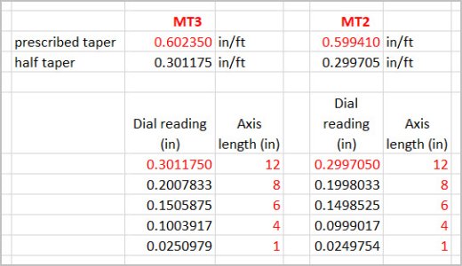
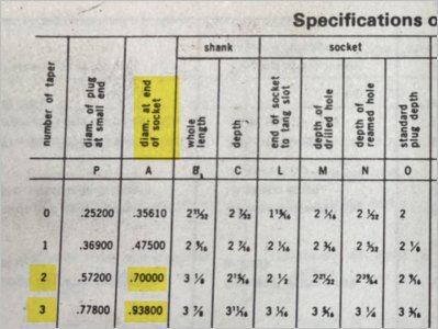
For the #2 Morse taper look at the chart and it is very close to .6” per foot. Set your taper attachment very close that (you can read the dial on the attachment (top scale) is roughly 6).
Adjust the top and bottom screws (the ones with the Allen head) to achieve a zero reading as you pass the apron back and forth on the Dead Centre. On our taper attachments there are two nuts that need to be loosened in order to swing the attachment back and forth. After that you should be good to go.


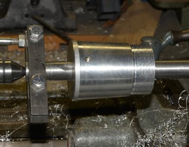
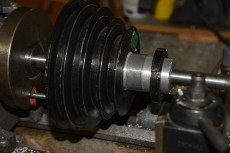
When I made your tailstock spindle I made a #2 Morse taper blank, dialled it in on the 4 jaw, mounted your spindle on the taper so it was centred on the taper. I then turned it between centres so it was as bang on as possible.
The #3 is “close” but will not dial into Zero - you will be off a couple thou and only get contact at the neck leaving the tail wagging - LOL
For the #2 Morse taper look at the chart and it is very close to .6” per foot. Set your taper attachment very close that (you can read the dial on the attachment (top scale) is roughly 6).
Adjust the top and bottom screws (the ones with the Allen head) to achieve a zero reading as you pass the apron back and forth on the Dead Centre. On our taper attachments there are two nuts that need to be loosened in order to swing the attachment back and forth. After that you should be good to go.
When I made your tailstock spindle I made a #2 Morse taper blank, dialled it in on the 4 jaw, mounted your spindle on the taper so it was centred on the taper. I then turned it between centres so it was as bang on as possible.
The #3 is “close” but will not dial into Zero - you will be off a couple thou and only get contact at the neck leaving the tail wagging - LOL
")