-
Scam Alert. Members are reminded to NOT send money to buy anything. Don't buy things remote and have it shipped - go get it yourself, pay in person, and take your equipment with you. Scammers have burned people on this forum. Urgency, secrecy, excuses, selling for friend, newish members, FUD, are RED FLAGS. A video conference call is not adequate assurance. Face to face interactions are required. Please report suspicions to the forum admins. Stay Safe - anyone can get scammed.
-
Several Regions have held meetups already, but others are being planned or are evaluating the interest. The Calgary Area Meetup is set for Saturday July 12th at 10am. The signup thread is here! Arbutus has also explored interest in a Fraser Valley meetup but it seems members either missed his thread or had other plans. Let him know if you are interested in a meetup later in the year by posting here! Slowpoke is trying to pull together an Ottawa area meetup later this summer. No date has been selected yet, so let him know if you are interested here! We are not aware of any other meetups being planned this year. If you are interested in doing something in your area, let everyone know and make it happen! Meetups are a great way to make new machining friends and get hands on help in your area. Don’t be shy, sign up and come, or plan your own meetup!
You are using an out of date browser. It may not display this or other websites correctly.
You should upgrade or use an alternative browser.
You should upgrade or use an alternative browser.
MT3 V.S. MT2
- Thread starter YYCHM
- Start date
I think what you mean is this surface is awkward to hold & twist right? When you were saying 'taper' I was thinking Morse taper segment inside the quill barrel
I've been referring to the whole dead center as the taper, I think that's the confusion LOL. I'll turn another sample as a test piece.
RobinHood
Ultra Member
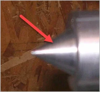
You could always add a couple of flats for a spanner high up on the point (red arrows). That would allow you to give it the 1/4 to 1/2 turn you need to get a better image of your blueing test.

Having flats up that far on the point will not change the functionality as one rarely ever uses the center that deep into a part ( it could happen with tubing, I suppose).
At least you would be able to see how you did with your angles of the MT 2 / MT3. Then you can always make another one with all the info you have learned from this attempt.
I wanted to revisit this MT2 v.s. MT3 issue so yesterday I turned another taper using what I thought was MT3 setup.

This time I used a longer piece of 3/4" stock and very carefully turned the small OD to 0.572".
Well it ends up it's not a very good MT2 approximation at all (or MT3 for that matter) The distance to the large 0.7" OD is 2.765" when is should be 2.56". This makes the taper angle 1.35 deg when it should be 1.4307 deg.

I blackened the taper with a felt marker to do a rub test. That silly thing was sticky for a good 3 hours so we won't try that again LOL.

This is the rub test in my tailstock spindle. That's the same location where my chuck taper gets chewed up, but interesting enough I can't perceive any wobble or slack with the taper mounted.

This is the rub test in a MT3/MT2 sleeve I have. I had to shorten the taper in order to get it to seat as it bottomed out in the sleeve.
So I guess I'm going to have to figure out how to dial the taper attachment in using a DI, as the TPF/Deg scale on it is just not fine enough.
This time I used a longer piece of 3/4" stock and very carefully turned the small OD to 0.572".
Well it ends up it's not a very good MT2 approximation at all (or MT3 for that matter) The distance to the large 0.7" OD is 2.765" when is should be 2.56". This makes the taper angle 1.35 deg when it should be 1.4307 deg.
I blackened the taper with a felt marker to do a rub test. That silly thing was sticky for a good 3 hours so we won't try that again LOL.
This is the rub test in my tailstock spindle. That's the same location where my chuck taper gets chewed up, but interesting enough I can't perceive any wobble or slack with the taper mounted.
This is the rub test in a MT3/MT2 sleeve I have. I had to shorten the taper in order to get it to seat as it bottomed out in the sleeve.
So I guess I'm going to have to figure out how to dial the taper attachment in using a DI, as the TPF/Deg scale on it is just not fine enough.
Last edited:
That should be easy you have a taper attachment by the looks of it, look up taper per inch then put your indicator on move the lathe 1” and look at the dial adjust till you get what you want. Did I say taper attachment ya lucky B!
View attachment 18984
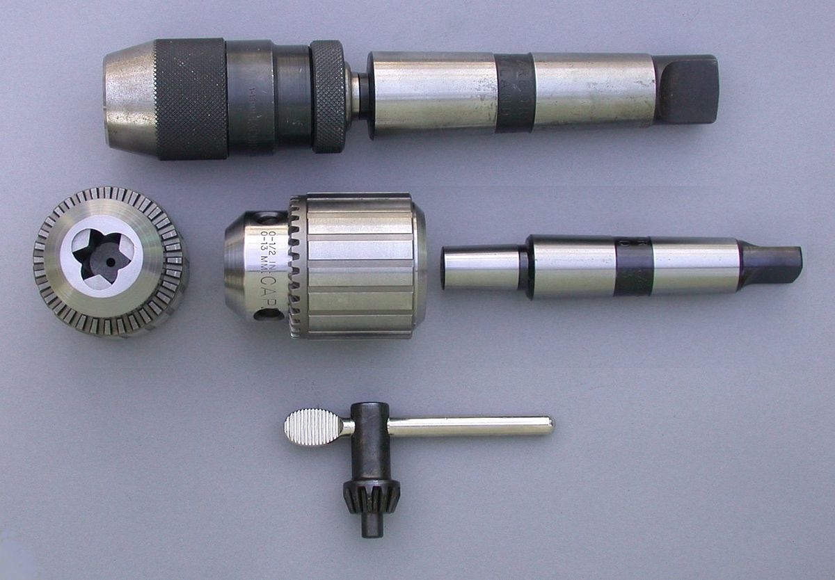
Will you leave enough on the rear for a tang?
I don't have anything that takes a tang.
Ok my drill chucks have them it’s in case of spinning in the taper it’s just something to consider.
And also a way to remove the Taper using a wedge in the tang slot.
Ok my drill chucks have them it’s in case of spinning in the taper it’s just something to consider.
I wish, I'm forever spinning my chuck taper out in my tailstock..... Your tail stock spindles accept a tang?
Last edited:
Your tail stock spindles accept a tang?
Yup, mine does.
Two ways to remove the Taper. Retract the quill till it gets pushed out, or extend the quill and use a wedge in the slot that magically appears.
Tangs won't rotate so you have to align them in the receiver till they go in.
There's a couple of things to unpack here, but lets start with the MT3 dimensions. You have a choice of defining 2 of 3 parameters: Big diameter, Length, Small diameter. Which are the 2 you want (the remaining one is a calculated result). For example...(sketch)
I don't think setting the angle bar by the gradation line is going to be reliable unless you are lucky. If you happen to have a reliable cylindrical bar with center drill ends, I would set it up in lathe with DTI on saddle, traverse 12" & adjust taper bar so the total deflection is 1/2 of 0.60235 = 0.3012". The reason for traversing this distance A) nice & long so very accurate B) matches the reference value in Machineries handbook. Of course you can scale it down if your taper isn't that long.
Actually back up a step - when was the last time you checked your tailstock in/out centering relative to spindle axis? If this is out, then it affects your angle bar setup too. And I don't mean lining up the centers by eye, I mean with an indicator swinging either side of the TS center.
I can check in the shop but think my marker is Sharpie brand. I've used others too. It dries nearly instantly so I don't know what to say about 3 hours. That's crazy. Is it a whiteboard marker or something different? Oily surface maybe?
Your localized rub stripe is confirming that your diameters are not matching target MT dimensions. The taper is not set right yet. Being stuck in the socket with only small rub band of interference is pretty much meaningless. I bet if you shoved it in at a slightly different angle it would stick there too but of course it would be pointing in a completely different direction every time, so not the makings of a good 'center'. Once you have the bar set up I bet you can get half the length rubbing off & you are within fine finishing mode for a perfect fit. Try it with a 'real' (commercial) ground/polished taper arbor & see what it looks like. If the socket is in decent shape the rub should be quite uniform. THAT is what you are trying to replicate.
I don't have a tang receptacle on my 14x40 TS either, many lathes don't. I usually have the opposite problem, it sticks too good on occassion.
Attachments
Last edited:
Actually this sketch/discussion might help both YYCHM & me.
Does anyone have the 'official' MT3 layout in terms of how the 0.60235 inch per foot is referenced? I got that number from Machineries Handbook which I think is trustworthy source. The 'numbers' are documented but I have yet to come across a sketch showing the 'foot (12") reference. Does it correspond to the centerline distance like sketch & therefore perpendicular offset = 0.60235/2=0.301175" as shown? Or is 12" along the taper hypotenuse which results in slightly different angle values. The difference is small, out beyond a few decimal places. But I've noticed half the numbers on the interweb seem different & that bugs me. Its supposed to be the same MT#.... unless there is a metric MT ha-ha. Sometimes the math doesn't compute either way. Won't affect anything in my shop, but just curios for historical interest. What was Morse thinking with all these crazy angles anyways?
Does anyone have the 'official' MT3 layout in terms of how the 0.60235 inch per foot is referenced? I got that number from Machineries Handbook which I think is trustworthy source. The 'numbers' are documented but I have yet to come across a sketch showing the 'foot (12") reference. Does it correspond to the centerline distance like sketch & therefore perpendicular offset = 0.60235/2=0.301175" as shown? Or is 12" along the taper hypotenuse which results in slightly different angle values. The difference is small, out beyond a few decimal places. But I've noticed half the numbers on the interweb seem different & that bugs me. Its supposed to be the same MT#.... unless there is a metric MT ha-ha. Sometimes the math doesn't compute either way. Won't affect anything in my shop, but just curios for historical interest. What was Morse thinking with all these crazy angles anyways?
Attachments

I believe that the original Morse taper as set by Mr Morse himself was not a measurement of the difference in diameter but rather was a specific angle of 2 degrees 50 minutes. I recall that this angle was chosen to arrive at a grade of 5%, but I can't make perfect sense of that just off hand.
By my math, a 5% grade actually has an angle of 2 degrees 51.6 minutes. Which is pretty darn close to the 2 degrees 50 minutes that I remember. Maybe it's "close enough???
I was also told that this angle was arrived at experimentally as optimum for good solid thrust retaining as well as ease of disassembly. Less angle would stay together well, but couldn't be disassembled easily. If so, then surely 51.6 degrees really is close enough to 50, so why keep an awkward number..... Though 5% is probably less awkward than 50 minutes.......
On reflection, I wonder if this small difference might be the variation that you have experienced @PeterT ?
Other tapers with different angles (eg Jacobs) claim the same benefit though so.....
Recall, that Morse tapers were (and still are) primarily used for thrust applications (drill press, etc).
I think it's relevant to know that Morse was also the guy who invented twist drills and the original drills were made with Morse taper arbours.....
I suspect that the different angles you see everywhere are the result of the medical industry playing around with the numbers to achieve good bone interference fits for joint and bone osteoplasty which didn't work well using the original angles because of the dissimilar materials.
Coincidentally, I learned this latter fact from a bone prosthetic specialist I met in Edmonton. I stayed at his house while I judged a dog trial East of there. I accept what he told me.
In other words, there is no magic in the Morse Taper standard. It's kind of like the original foot or even the new meter (both just arbitrary numbers) one original based on the King's foot size and the other based on a specific arbitrary conversion of one inch = 2.54 cm.
Anyway, thats my old memetic version of the Morse Taper for whatever that is worth. It may or may not be correct.
Last edited:
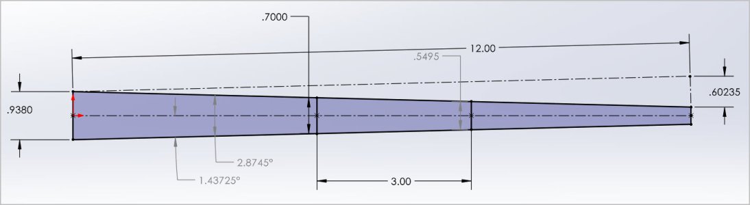
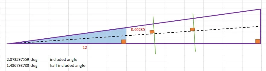
My Machinery handbook doesn't mention MT angles, only the inch per foot taper (and inch per inch which is same thing). So if one assumes that those are the defining parameters & its the typical rise over run, it might yield a picture like attached. Blue shade shows the 2 reference dimensions, 0.60235 over 12" (1 foot) assuming a right triangle. That works out to angles shown in degrees. Which equates to 1deg-26min-12.48sec and 2-deg-52min-24.95sec. So no nice round number love there.
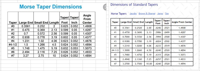
I assumed the larger (purple) triangle extension is how any MT arbor could be extracted within whatever (green lines) combination of length or diameter, but preserving the sacred angles of course. But the arbor green lines would be perpendicular to center (dash) line indicated by orange right angle box. I have no idea if this is 'the way'. It seems logical but as mentioned, rarely matches other references on the net. These tables show an angle with slightly different degrees.
I assumed the larger (purple) triangle extension is how any MT arbor could be extracted within whatever (green lines) combination of length or diameter, but preserving the sacred angles of course. But the arbor green lines would be perpendicular to center (dash) line indicated by orange right angle box. I have no idea if this is 'the way'. It seems logical but as mentioned, rarely matches other references on the net. These tables show an angle with slightly different degrees.
Attachments
Last edited:
Machine taper - Wikipedia
I'm not clear what ref 'taper' angle of1:19.922 represents, that is 1.316923 deg equivalent
Clear as mud. Maybe someone snuck in a metric Morse taper when nobody was looking LOL
Attachments
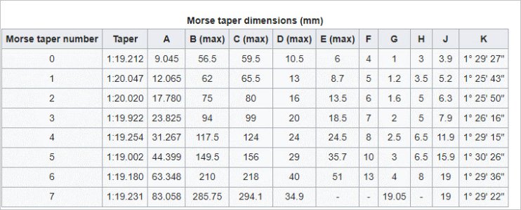
another vote for 1-26'-16" (=1.437778 deg)
...or are they just copying one another?
CGTK - Morse Taper Dimensions
www.cgtk.co.uk
...or are they just copying one another?
Dialing it in how?
This is what I was referring to when I said that it takes time to 'dial' it in. My taper attachment has the TPF/Deg scale...... which is like saying the snow outside is an indicator of cold. It's a good indicator, but not precise. I use my DRO + some dial indicators (as corroborating measurements) to measure the taper over 1 inch of travel. I tend to overthink this part and repeat it many times until I realize the first or second position was the best.So I guess I'm going to have to figure out how to dial the taper attachment in using a DI, as the TPF/Deg scale on it is just not fine enough.
My problem is that I don't use the attachment enough, so it doesn't get exercised enough and thereby is not 'fluid' in motion. The next issue is the adjustment thumbscrew needs waaaay too much pressure, the lock nuts end up affecting the taper etc. But..... with persistence I've managed to get it very very close to the published tapers in Machinery's Handbook.
To anyone reading ---- please advise if there is something obvious to improve on this process.
I've made a tapered arbour for a tapping chuck to fit my MT3 tail stock without a taper attachment. The method I used may have been mentioned in previous posts But here goes
1 align the tail stock to the head stock with a known reference bar, I use an and Edge Technologies 12 " alignment bar
2 Chuck up some scrap in the 3 jaw chuck and put a center in with a center drill.
3 put a dead center in the tail stock
4 Put a known MT3 dead or live center between the scrap piece center and the tail stock center
5 set your tool post perpendicular, or close to it. to the arbour that's between centers, lock the post down, don't move it.
5 attach a DTI tenths indicator to the compound, and adjust the angle of the compound till you get zero deflection on the indicator as you traverse towards the chuck, lock the compound.
6 your angle is now set to replicate the good known taper.
leave lots of length on the arbour your machining. From the pictures that were posted the taper seems too short , not leaving enough material to spin the taper in the tail stock. as mentioned earlier you could mill some flats in order to grab it. Use some Dykem Hi spot or Prussian blue to check the fit.
If you have a tool post grinder you can grind the OD of the new arbour, be sure not to move the compound or tool post prior to using the grinder.
Hope this helps, as my written explanation may have a lot to be desired
DPittman
Ultra Member
Interesting to think that there might be different numbers for the same thing. I've got one of those lathe test bars with a morse taper on each end, one for tailstick and one for headstock and the one for the headstock (mt3) has never fit worth a s%$#. I've always blamed the original (India) for a quality control issue.another vote for 1-26'-16" (=1.437778 deg)
CGTK - Morse Taper Dimensions
www.cgtk.co.uk
...or are they just copying one another?