@YYCHM i‘ve been wondering if a DRO makes the round column issue disappear. What’s your experience?
Disappear in what way?
@YYCHM i‘ve been wondering if a DRO makes the round column issue disappear. What’s your experience?
I assume that if you have a position that you can re-zero the DRO to, then losing position when raising and lowering the head wouldn’t be an issue. It would be a bit of a PITA to have to re-zero though.
@YYCHM i‘ve been wondering if a DRO makes the round column issue disappear. What’s your experience?
 )
)Hee hee, I can TOTALLY relate to that!Or worse yet I realize its the same idea I had 4 years ago & already forgot about it so it seems new again.
I don't think so John. The work is DRO registered in XY but the mill head has no idea where it is relative to spindle axis once its been raised or lowered around the post & potentially swiveled round it. That's why the stabilizing arms or other mechanical fixes.
But you know.... assuming the head can only drift by pivoting around the post (vs any nod or tram change as a function of being raised or lowered) - if you could hook up a sensitive 'radial' displacement DRO so the mill head knows where it was relative to the post, that might work. Click zero/null before raising head, raise head, display says drifted 1.2345 degrees. This time, rather than kick the cat, rotate back to 0.000 readout, lock head. Theoretically its back inline relative to table XY work which hasn't changed. The trick is you need some kind of zero reference encoder strip up the entire column that wont interfere with normal movement.
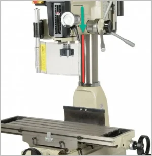
That would be accurate enough for a drill press but not a milling machine... at least in my opinion.Looking at Peter's photo, lets say you could scribe a true line up and down the column to the right side when facing the mill. True the mill head then put a matching mark to marry up with the column scribe. As long as the head mark matches the scribe you should be in business whenever the head is raised or lowered. Or did I miss something with this thinking???
Of course the column and spindle need be on the same plane which one assumes they are from factory.
That would be accurate enough for a drill press but not a milling machine... at least in my opinion.
I believe you are correct. With the added step of re-zeroing to the same corner, I believe you would have the same starting reference point - within the accuracy of your edge finding. I like it!I’m not sure that I agree. For example if you always re-zero to a corner of your workpiece then any x/y dimension from that corner should be correct. Even if you rotate the head once you re-zero it should work. Am I missing something?
This is the sort of thing I have run into.
Have found the center of something I need to drill with a center finder, I zero my DRO. Now I go to mount the drill bit only to find that the work piece is too tall to accommodate the drill bit. The only solution is to raise the head. So I raise the head to accommodate the drill bit but now my zero might be out and I have to relocate zero with the center finder. The head is now too high to accommodate milling and have to lower it again and go through the same zeroing process. PITA. Doesn't happen often but does occur from time to time. Getting a stubby set of drill bits has eliminate a lot of that nonsense but not always.
This is the sort of thing I have run into.
So I raise the head to accommodate the drill bit but now my zero might be out and I have to relocate zer The head is now too high to accommodate milling and have to lower it again and go through the same zeroing process. PITA. .