• Scam Alert. Members are reminded to NOT send money to buy anything. Don't buy things remote and have it shipped - go get it yourself, pay in person, and take your equipment with you. Scammers have burned people on this forum. Urgency, secrecy, excuses, selling for friend, newish members, FUD, are RED FLAGS. A video conference call is not adequate assurance. Face to face interactions are required. Please report suspicions to the forum admins. Stay Safe - anyone can get scammed.

METAL LATHE SMOKE, RPM LOSS, NEW LATHE MOTOR?

My train of thought on this is work more with less effort, hence the two HP, the max rpm for my lathe is about 1330 ( need to look again) per the face plate and belt change selections. I'm not trying to create a big machine outa a little one, I just want to have the oomph and energy and slightly improve on what I have; you can run a marathon with a rucksack or you can run a marathon with a fanny pack, am I wrong here?

I guess that depends on what you mean. Lots of ways to interpret it.

You burned out a motor, so naturally you suspect the motor wasn't big enough and more is better. So if you mean the motor can work better with less effort. You are correct. But if you mean the lathe can work better with less effort, that's not a great idea.

One way to measure how hard a lathe is working is to measure its current flow on the mains side. Generally speaking, a lathe will see its highest current when you spin it up - it takes a lot of power to overcome all that inertia. But the quicker you spin it up, the more current will be required. Most gears can handle more than the design power, but only to a limit. If you double the gear forces, something might break. We don't want that. By programming the VFD to slow the acceleration, you can keep the gear forces within the design envelope during spinup and lessen the strain on the motor too.

Look at it this way. If you put a Harley engine on a scooter, it might be able to take the weight but it won't be able to handle full power. The engine will be fine, but not the scooter cuz it wasn't designed for that much power. You have to keep the power down to keep the scooter going. Same as your lathe. Keep the power down during the spin up and don't try to cut more or bigger chips than the original motor could. This way you have a motor that will last forever and a lathe that won't complain when it's used near its limits. That's sorta my rationale for 50% more power, not double. It's one thing to replace a motor, but quite another to repair broken or stripped gears.

Thank you for the offer, if I get stuck I'll hit u up for help, the link posted earlier (Clough) really nails it,

I and others are looking forward to helping you. Btw, I think Clough42 has a TECO VFD too.

I am looking forward to getting rid of all the wiring octopus from the factory, pic below.

What I am doing with my lathe is making sure all the wires are correctly labelled and then changing their connections to operate with the VFD. I don't plan to remove the rest of the circuitry. That way I can always revert back to the original design.
 
EDIT, from reading/research this motor is vfd rated, but I'm no expert...cheers

Where did you see that? I read the specs and didn't see it. A VFD rated motor would be better, and also give you a wider operating range for rpm, but I'd expect it to cost a lot more too - maybe double. Most guys don't think that's worth it.
 
thank you,
My train of thought on this is work more with less effort, hence the two HP, the max rpm for my lathe is about 1330 ( need to look again) per the face plate and belt change selections. I'm not trying to create a big machine outa a little one, I just want to have the oomph and energy and slightly improve on what I have; you can run a marathon with a rucksack or you can run a marathon with a fanny pack, am I wrong here?

Thank you for the offer, if I get stuck I'll hit u up for help, the link posted earlier (Clough) really nails it, I am looking forward to getting rid of all the wiring octopus from the factory, pic below.

As for the VFD rated motor, should I go back and look for something else, E Motors claimed it was a good combination, in reality a few bucks more (if reasonable) would be a better combination...no?

I guess that depends on what you mean. Lots of ways to interpret it.

You burned out a motor, so naturally you suspect the motor wasn't big enough and more is better. So if you mean the motor can work better with less effort. You are correct. But if you mean the lathe can work better with less effort, that's not a great idea.

One way to measure how hard a lathe is working is to measure its current flow on the mains side. Generally speaking, a lathe will see its highest current when you spin it up - it takes a lot of power to overcome all that inertia. But the quicker you spin it up, the more current will be required. Most gears can handle more than the design power, but only to a limit. If you double the gear forces, something might break. We don't want that. By programming the VFD to slow the acceleration, you can keep the gear forces within the design envelope during spinup and lessen the strain on the motor too.

Look at it this way. If you put a Harley engine on a scooter, it might be able to take the weight but it won't be able to handle full power. The engine will be fine, but not the scooter cuz it wasn't designed for that much power. You have to keep the power down to keep the scooter going. Same as your lathe. Keep the power down during the spin up and don't try to cut more or bigger chips than the original motor could. This way you have a motor that will last forever and a lathe that won't complain when it's used near its limits. That's sorta my rationale for 50% more power, not double. It's one thing to replace a motor, but quite another to repair broken or stripped gears.


I and others are looking forward to helping you. Btw, I think Clough42 has a TECO VFD too.


What I am doing with my lathe is making sure all the wires are correctly labelled and then changing their connections to operate with the VFD. I don't plan to remove the rest of the circuitry. That way I can always revert back to the original design.
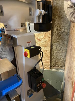
the motor burned out because of age I'm thinking, I have had less that 5 hrs on the lathe, I have no idea what the previous owner has done, when I got the lathe the contactors would not release, so I cleaned them, everything was working great until I put it into high gear to practice making some shiny cuts.

Good points on the power, I'm not trying to make a Ferrari out of a Ford....😉 (good name for a movie), Clough42's videos are awesome and easy to understand with the vfd.

good tinking and my thoughts as well;

"This way you have a motor that will last forever and a lathe that won't complain when it's used near its limits. That's sorta my rationale for 50% more power, not double. It's one thing to replace a motor, but quite another to repair broken or stripped gears".

As for the circuitry in the original format, anyone want it? I would far rather wire this up like the B/Bee mill, forward/reverse, emergency stop and power button. This lathe is a bit of a nightmare with the wiring for something so simple and the mill wiring proves it, so the offer is there if anyone wants the electrics.
 

Attachments

  • IMG_6792.JPG
    IMG_6792.JPG
    2.2 MB · Views: 1
Where did you see that? I read the specs and didn't see it. A VFD rated motor would be better, and also give you a wider operating range for rpm, but I'd expect it to cost a lot more too - maybe double. Most guys don't think that's worth it.
I actually AI'd it, but AI is not always on the ball;

AI;

Search Assist

Yes, the Brook Crompton BC4N002V4 motor is rated for use with variable frequency drives (VFDs), making it suitable for applications that require speed control. It is designed for general purpose and severe duty applications. tristate-bearing.com esrcommerce.com

Brook Crompton BC4N002V4 Motor Specifications​

General Information​

  • Model: BC4N002V4
  • Type: AC Electric Motor
  • Horsepower: 2 HP
  • Speed: 1740 RPM
  • Voltage: 230/460 VAC
  • Phase: 3-Phase
  • Frequency: 60 Hz

VFD Compatibility​

  • Duty Rating: Suitable for VFD (Variable Frequency Drive) applications
  • Enclosure Type: Totally Enclosed Fan Cooled (TEFC)
  • Service Factor: 1.25
  • Efficiency: Premium efficient design
  • Insulation Class: Class F

Additional Features​

  • Frame Size: 145T
  • Frame Material: Cast Iron
  • Ingress Protection: IP55 rated
  • Ambient Temperature Range: -20 to 40°C
  • Warranty: 3-Year Warranty
The Brook Crompton BC4N002V4 motor is designed for general purpose and severe duty applications, making it suitable for use with VFDs. Its robust construction and efficiency ratings enhance its performance in variable speed applications.
 
That motor is obviously suitable for use with a VFD.

When thinking about using a non inverter rated motor with a VFD ( Which I have done quite successfully). A few things to keep in mind.

Demands for typical hobby use vs. industrial use are usually very different.

1) Cooling. On both my mill and drill press this has never been an issue, even after doing an hour of really slow operations my motors get comfortably warm at best, case temperature perhaps 40 deg C. I would guess the internal hot spot temperature to be 10-20 degrees warmer. I don't use an external fan.

2) Insulation temperature rating. Typically VFD rated motors use either class F (155 deg C), or class H (180 deg C) insulation. Older or cheaper motors use class A or B (105-130 deg C) insulation. My Lenmark surplus (new for $100) motor has class F insulation and my $50 ebay special retired comercial dryer motor has class B insulation. All good after many years.

2) Insulation voltage rating. VFDs do generate more of a fast edge square wave with voltage spikes not a clean and gentle sinewave like the power system, That being said enameled wire can typically withstand 2400-7000V before breaking down. So insulation voltage rating is more important when using higher voltage motors for example a 600V motor. When using a 240V motor you have more wiggle room. Keep in mind longer lines between the motor and source increase those edge spikes, so don't use excesively long motor leads. I read a study where they added VFD's to all 3P motors in a large factory, with hundrerds of very old non VFD rated motors, they actually found motor failures decreased because the transients applied to the motor windings actually went down in cases where the motor was connected to a bus with very long lines.

3) Bearings. Inverter-rated motors often have a ground strap on the shaft and/or isolated bearings. So far, the bearings on both of my non-inverter-rated motors seem to be just fine. YMMV.
 
Entirely possible. Depends on the layout of your shop wiring and the filtering and sensitivity built into your DRO.

RF noise from the motor wiring isn't a likely problem unless the cable is long. That's what they say anyway. I shielded it anyway.

But noise on the input wiring from the VFD is always a risk. My advice is simple - filter the input wiring regardless and run the VFD off of its own circuit (if you can) from the breaker box - or at least don't share it with electronics.

Suit yourself on shielded cable to the motor, but make sure it is stranded wire and heavy enough gauge. I did it just because there was so much noise on it not because it was creating any interference.

BTW, it has not been said here, but all power switches and relays should be on the input side of the VFD from the mains, NOT EVER on the output side to the motor. Let the VFD turn the motor on and off and reverse it. Don't use switches or relays in the motor wiring.
Hi Susquatch,

I whole heartedly agree with you, I've seen several dead VFD's because of switches on the output side. Some people get away with it !

As far as input line noise is concerned, because all electronic devices are mandated to have line input chokes here it is not an issue. However if the VFD to motor wiring is kept short it should not be a problem. Screened cable between the VFD & motor does help and will reduce future problems due to radiated interference. The most obvious one is when you can hear it on an AM radio, sounds like an angry bee !

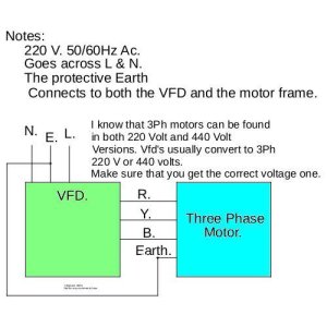
Re my picture, yes delete it and replace with the one below. I had missed the line between the two boxes.
VFD Info.jpg
 
thank you,
My train of thought on this is work more with less effort, hence the two HP, the max rpm for my lathe is about 1330 ( need to look again) per the face plate and belt change selections. I'm not trying to create a big machine outa a little one, I just want to have the oomph and energy and slightly improve on what I have; you can run a marathon with a rucksack or you can run a marathon with a fanny pack, am I wrong here?

Thank you for the offer, if I get stuck I'll hit u up for help, the link posted earlier (Clough) really nails it, I am looking forward to getting rid of all the wiring octopus from the factory, pic below.

As for the VFD rated motor, should I go back and look for something else, E Motors claimed it was a good combination, in reality a few bucks more (if reasonable) would be a better combination...no?

EDIT, from reading/research this motor is vfd rated, but I'm no expert...cheers
Hi Guys,

In general hobbyists don't really need VFD rated motors ! These are more for industrial applications. The simple answer is keep an eye on the motor temperature. If it gets so hot that you can't place your hand on it comfortably then just switch it off, or remove the load and increase the motor speed to shift more cool air over it.

Industrial VFD rated motors tend to have a separately powered fan running continuously just to keep the motor cool.
 
Hi Guys,

In general hobbyists don't really need VFD rated motors ! These are more for industrial applications. The simple answer is keep an eye on the motor temperature. If it gets so hot that you can't place your hand on it comfortably then just switch it off, or remove the load and increase the motor speed to shift more cool air over it.

Industrial VFD rated motors tend to have a separately powered fan running continuously just to keep the motor cool.
I did notice Clough42 in his vfd video added a pc fan to the motor via the vfd and gave it some parameters to run on, pretty neat stuff.
 
the motor burned out because of age I'm thinking,
Umm, have you taken apart the old motor? As I posted early on, I would bet the motor just needs a new capacitor and a bit of cleaning. Bearings are optional but...why not?

Even if you go the VFD route, a working 1 hp motor is never a bad thing to have around.

If the windings really are burnt, they will smell like an old house fire--nasty burnt plastic or similar.

Craig
 
Yes, the Brook Crompton BC4N002V4 motor is rated for use with variable frequency drives (VFDs), making it suitable for applications that require speed control. It is designed for general purpose and severe duty applications.

I see now. I think it is important to distinguish between VFD Compatible and VFD Rated. As @slow-poke says this motor is clearly compatible with a VFD. I sure hope that nothing I said implies otherwise. It will work just fine and you will love it.

You will also note that I originally suggested +/- 25% frequency. I believe that is a safe operating range for a compatible motor like yours. It isn't a hard industry standard or anything. It's just a number that I have come to believe will work and a number that I feel comfortable recommending. Others might suggest different numbers.

On the other hand, a VFD Rated motor has a much wider frequency range. Typically, they are rated at 10:1 or 20:1 or 1000:1. This turn down ratio means that a rated motor can be safely operated at 1/20th of the operating frequency so 6hz for 10, 3 Hz for 20, and fully stopped for 1000. The Nidec motor I installed on my mill is rated at 1000:1. I can and have run it at full torque at virtually zero rpm. Among other features, a rated motor means it can handle that lower speed without needing fans or auxiliary cooling.

I had wanted to know where you saw it so I could change my rpm recommendations if appropriate. Since it is compatible but not rated, I'm still recommending a minimum of 45 Hz and a maximum of 75.

These limits can be programmed into the VFD. Your motor can also run slower than that if needed but then you have to keep an eye on the load and motor temperature to avoid damaging the motor and you may need to add things like cooling fans. @slow-poke makes some good recommendations there and so does Clough42. Keep in mind that your motor is fully sealed which is good for other reasons, but it also means that fans won't be quite as effective as they would be on an open motor.

About stripping your control box. If that's what you want to do, go for it. If you clear out enough space, you might even be able to mount your VFD in the cabinet but you will also need a cabinet fan. I bought my lathe new, so it is a relatively new lathe. I wanted to be able to return it to factory condition if I ever sold it.
 
Re my picture, yes delete it and replace with the one below. I had missed the line between the two boxes.

I think it would be better the other way around. Leave the connection between the motor and the vfd and remove the jumper between the input and output ground.

All of the VFDs I have seen provide both input and output ground connections. I do not know why because I don't have detailed internal schematics or an operating theory. But I suspect that is done so the two grounds can float relative to each other. This is common on many high frequency circuits where using a jumper can damage them.

The fact that two separate grounds are provided suggests that they should be used, but don't use a ground jumper.

The wiring diagram for my Teco's shows no jumper.

I'm somewhat jealous of your national standard for built-in input filtering.
 
I think it would be better the other way around. Leave the connection between the motor and the vfd and remove the jumper between the input and output ground.

All of the VFDs I have seen provide both input and output ground connections. I do not know why because I don't have detailed internal schematics or an operating theory. But I suspect that is done so the two grounds can float relative to each other. This is common on many high frequency circuits where using a jumper can damage them.

The fact that two separate grounds are provided suggests that they should be used, but don't use a ground jumper.

The wiring diagram for my Teco's shows no jumper.

I'm somewhat jealous of national standard for built-in input filtering.
It varies, but a single ground screw seems to be common. Though I have seen VFD's that have two ground screws into an alloy backing and heatsink plate.

Having two separate floating grounds is a very bad idea ! That means that you have no control over them.
 
It varies, but a single ground screw seems to be common. Though I have seen VFD's that have two ground screws into an alloy backing and heatsink plate.

All of my VFDs have separate grounds

Having two separate floating grounds is a very bad idea ! That means that you have no control over them.

Normally, I would totally agree with you. I am an automotive engineer who specialized in vehicle electronics. Floating grounds are almost always a bad idea.

But, there are exceptions. You are forcing me to go a bit deeper here. I don't normally like to do that.

Floating grounds are often intentionally used in sensor circuits, switching circuits, and transformer circuits. It depends on the application. For example, many oscilloscopes have floating grounds and use power cords with no ground for good reason. The last thing you ever want to do is short circuit a high ground to a low one in a scope. You can even buy signal isolators to prevent that. Again, I could go a lot deeper but I don't like to.

I'm just saying that the installation diagrams for my VFDs have separate grounds and do not show a jumper. When in doubt, trust the manufacturer. It's unlikely that we know more than they do.

A VFD is basically a switching device. See @jcdammeyer's description above. It is possible and perhaps even likely that the manufacturer wants or needs the output ground to float from the input in order to capture the full voltage range in the output. In other words, wants the entire signal to reference its lowest voltage which might be negative relative to the input ground. If you connect these grounds, you lose a portion of its range - not to mention the chance of high resulting currents internally.

On the other hand, it's possible that both grounds are internally connected to a common point (a heat sink or chassis). We don't know. If so, you don't need the jumper anyway because the chassis is the jumper!

If you can show me a North American manufacturer's VFD wiring drawing that shows a jumper, I would be interested in exploring it.

For the time being, my advice is no jumper.
 
All of my VFDs have separate grounds


Normally, I would totally agree with you. I am an automotive engineer who specialized in vehicle electronics. Floating grounds are almost always a bad idea.

But, there are exceptions. You are forcing me to go a bit deeper here. I don't normally like to do that.

Floating grounds are often intentionally used in sensor circuits, switching circuits, and transformer circuits. It depends on the application. For example, many oscilloscopes have floating grounds and use power cords with no ground for good reason. The last thing you ever want to do is short circuit a high ground to a low one in a scope. You can even buy signal isolators to prevent that. Again, I could go a lot deeper but I don't like to.

I'm just saying that the installation diagrams for my VFDs have separate grounds and do not show a jumper. When in doubt, trust the manufacturer. It's unlikely that we know more than they do.

A VFD is basically a switching device. See @jcdammeyer's description above. It is possible and perhaps even likely that the manufacturer wants or needs the output ground to float from the input in order to capture the full voltage range in the output. In other words, wants the entire signal to reference its lowest voltage which might be negative relative to the input ground. If you connect these grounds, you lose a portion of its range - not to mention the chance of high resulting currents internally.

On the other hand, it's possible that both grounds are internally connected to a common point (a heat sink or chassis). We don't know. If so, you don't need the jumper anyway because the chassis is the jumper!

If you can show me a North American manufacturer's VFD wiring drawing that shows a jumper, I would be interested in exploring it.

For the time being, my advice is no jumper.
Hi Susquatch.

I see where you are coming from.
I see the induced voltage from an ungrounded motor as a potential danger. All the VFD's that I've worked on/with do not have an external connection with a floating ground. Even the ones with two ground terminals, the two ground terminals are always commoned.

Indeed the VFD provides an isolated voltage source output. This is inherent in its design. The input output isolation is tested to at least 2.5Kv
 
All the VFD's that I've worked on/with do not have an external connection with a floating ground.

Might be another UK difference.

Or it might be an internal common. Who knows.

My advice is always to do what the manufacturer says to do.
 
Umm, have you taken apart the old motor? As I posted early on, I would bet the motor just needs a new capacitor and a bit of cleaning. Bearings are optional but...why not?

Even if you go the VFD route, a working 1 hp motor is never a bad thing to have around.

If the windings really are burnt, they will smell like an old house fire--nasty burnt plastic or similar.

Craig
I will keep it handy and go through it when the opportunity arrises, someone always needs a working motor or who know what will show up here next that needs a motor. (where's the thumbs up emoji?)
 
One think to keep in mind is that in North America, there are two common ways in which domestic AC electric supply is provided. You might get 2 of three phases or a 120, 208 service. Or you might get a 120 / 240 split tap. In my experience, the two of three phases is more common, but I have seen both; And I have seen nothing outside of major cities.

Bonded versus isolated grounds are a psudo religious issue. I prefer bonded grounds as a general rule, but I am not prepared to argue one way or another

Outside of North America, other voltages and frequencies are used, but RMS allows the power calculation to be as simple as with a DC circuit. And that root 2 factor is a universal one because of of the integral of the sine wave
 
If you have any specific questions I can help, if you want. The guys look like they are all over this so I’m not gonna butt into a process that is well on its way.
just ordered the new motor and vfd, lots of real world experience here, pretty amazing actually. E Motors Canada was really helpful and as I understand it knows this forum quite well.

ps......
I actually thinks some of these guys are only here to help spend other guys money as their own wives have their credit cards locked tighter than a Medieval Chasity belt, I think it's working to be honest.....😉
 
Back
Top