• Scam Alert. Members are reminded to NOT send money to buy anything. Don't buy things remote and have it shipped - go get it yourself, pay in person, and take your equipment with you. Scammers have burned people on this forum. Urgency, secrecy, excuses, selling for friend, newish members, FUD, are RED FLAGS. A video conference call is not adequate assurance. Face to face interactions are required. Please report suspicions to the forum admins. Stay Safe - anyone can get scammed.

METAL LATHE SMOKE, RPM LOSS, NEW LATHE MOTOR?

After the very basic VFD install on my surface grinder, I got brave when doing my lathe.
A little fwd/rev switch rewiring, a pot & tach, a little 3d printing, et voila!

View attachment 69908

Funny thing, while ripping out the wiring for the drum switch I discovered that I had a 2-speed motor!
Nice,
I have found some really good videos thanks to the info here, there is the bench set up/test one with the addition of a "pot & reverse switch" excellent video, really all I need. I am impressed at how well you can "tune" the motor through the vfd, exciting times ahead...😉
 
A question;
I emailed E Motors Canada with my thoughts on a new motor and vfd, I have both 220/110 in the shop, I see that the vfd steps up 110 to 220 and I also see that E motors sells 220 vfd's when you scroll down under the motor selection, logic would dictate the 220 vfd is my correct option to pair with the new motor as 220 is the input?

When watching the bench test video he had 110 input and 220 output


A question;
I emailed E Motors Canada with my thoughts on a new motor and vfd, I have both 220/110 in the shop, I see that the vfd steps up 110 to 220 and I also see that E motors sells 220 vfd's when you scroll down under the motor selection, logic would dictate the 220 vfd is my correct option to pair with the new motor as 220 is the input?

When watching the bench test video he had 110 input and 220 output


The 110V input VFD will max out at 1hp output. I believe the best practice is to upsize the VFD 50% from the motor size.
If you have 220v available to you, that's the route I would take.
 
The 110V input VFD will max out at 1hp output. I believe the best practice is to upsize the VFD 50% from the motor size.
If you have 220v available to you, that's the route I would take.
Sounds good as I wanted to go from a dead 1hp to 2hp motor and kinda stumbled on the 220 in on the vfd, but was not aware that a 1hp motor is the limit of a 110 in vfd, thank you for that, it helps to clear up how it all works and with what.
 
Hi Guys,

Yes I've seen some of those chinglish handbooks/manuals ! Some look like they have been written by a tame monkey.

I'm particularly busy at the moment but I was thinking about doing a drawing explaining the connections. But as far as setting up any particular VFD, no I could only generalise.

Just a quick one, there are some very good low priced VFD's out of China. The Ecogoo is one and there are several others. The Ecogoo is quite well thought of and sold under various other names by the same manufacturer.
Hi Guys,

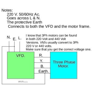
I had a spare half hour this morning, so I did a drawing of the connections between a VFD and the motor.
NOTE: I have made no attempt to explain how to wire external controls, these will be dependent on the manufacturer of the VFD you choose.

VFD Info.jpg
In the UK "N" would be the mains neutral, whilst "L" would be the live supply wire. In the USA and Canada I believe that the supply is a centre tapped 220 volts. The 220 volts should be wired to "L & N"

The other gotcha is both VFD's and 3 phase motors can be had in 220 volt and 440 volt ratings. Using the wrong one risks motor damage and possibly VFD as well.

VFD's work by rectifying the incoming AC voltage and usually providing a doubled DC voltage, ie 220 in 440 out. This DC voltage is then chopped at a frequency that sets the motor speed. High frequencies greater than 50/60 Hz will cause the motor to turn faster. Conversely a lower frequency will cause the motor to turn more slowly. Often you will find VFD rated motors that incorporate a fan driven by an independent motor, this is simply because as the motor is set to run more slowly less air can be blown through the motor by the internal fan.
 
Hi Guys,

I had a spare half hour this morning, so I did a drawing of the connections between a VFD and the motor.

I am not familiar with wiring standards in the UK. However, there are some differences between what you show and what is likely to be found here in Canada.

NOTE: I have made no attempt to explain how to wire external controls, these will be dependent on the manufacturer of the VFD you choose.

View attachment 69930
In the UK "N" would be the mains neutral, whilst "L" would be the live supply wire. In the USA and Canada I believe that the supply is a centre tapped 220 volts. The 220 volts should be wired to "L & N"

The other gotcha is both VFD's and 3 phase motors can be had in 220 volt and 440 volt ratings. Using the wrong one risks motor damage and possibly VFD as well.


In Canada, you can find 3phase wire that is Black/Red/Yellow like you describe. But it is more likely to be Black/Black/Black with a Green Ground. Other combinations are also common.

The important things are that the cable be:

1. the right gauge which depends on the cable length and HP of the motor,

2. be rated for 3ph operation at the required voltage and current,

3. that all motor connection wiring be flexible stranded cable not solid wire,

4. If necessary, it might also need to be shielded to reduce noise from the VFD which can damage other equipment.

High quality VFD Rated Cable is available from Mouser and Digi-Key. Digi-Key staff are VERY helpful and knowledgeable.

Unshielded stranded 3ph wire is also a available at places like Home Despot.

Your ground wiring drawing shows the mains ground connected to the motor ground. This is not a good idea. They should both be connected to the respective input and output grounds on the VFD. Other connection paths can create ground loops. With grounds, you want all ground currents to share a common path and not have choices between paths. Basically, ground current can generate voltage and these relative voltages can play havoc on adjacent circuits. It's best practice not to have them.

If the motor cable is shielded, the shielding (mesh/foil/ or both) should be connected to one location at one end but not both ends. I prefer to connect it at the VFD end because the VFD creates way more electrical noise than the motor does. This shielding is intended to prevent the power wires from acting like radio antennas inside your shop and affecting things like DROs, Bluetooth, Computers, Calculators, 3D Printers, phones, radios, etc.. When I measured the noise on my Mill VFD, I was mortified by how bad it was. Shielded cable clobbered that problem.

Mains side noise is also commonly encountered with VFDs. Sometimes you need to install mains side filters to prevent this noise from feeding back into your shop or home wiring. Digi-Key sells nice filters for this, or you can make your own with some iron cores.

VFD's work by rectifying the incoming AC voltage and usually providing a doubled DC voltage, ie 220 in 440 out.

I'd leave this DC 220/440 stuff out of your writeup. It will be what it will be and users don't need to know what it is because they might confuse it with different 3 phase voltage systems. Just stick with overall VFD input and output. Ie 220 single phase in, and 220 three phase out. If you feel you need to add the DC part just use it to say that is how they convert single phase to 3 phase as per your next piece as follows.

This DC voltage is then chopped at a frequency that sets the motor speed. High frequencies greater than 50/60 Hz will cause the motor to turn faster. Conversely a lower frequency will cause the motor to turn more slowly. Often you will find VFD rated motors that incorporate a fan driven by an independent motor, this is simply because as the motor is set to run more slowly less air can be blown through the motor by the internal fan.

And add that non-vfd rated motors may need extra cooling or conversely don't run them below 45 rpm or so.

If you want, you can repost your writeup and I'll delete the original and my comments.

I think it's a good idea to provide something like this. It's all covered elsewhere in the forum but I like it all in one place.

Another option would be to get a VFD Wizzard like @BaitMaster or another forum VFD guru to do a write up for us. Those guys do this stuff for a living and are 100% familiar with the Canadian Setting. He might also be familiar enough with all the different VFDs out there to make a generic setup guide for the controls too. Alternatively, you or I could do it based on our models - I have both Brand Name Tecos and Generic Chinese VFDs.

 
I am not familiar with wiring standards in the UK. However, there are some differences between what you show and what is likely to be found here in Canada.
Hi Susquatch,

I don't disagree with your comments at all, since I an not familiar with wiring conventions in Canada. I appreciate your comments.

In Canada, you can find 3phase wire that is Black/Red/Yellow like you describe. But it is more likely to be Black/Black/Black with a Green Ground. Other combinations are also common.
In the UK Red/Black/Yellow is very much common, not forgetting that Green with a yellow stripe is always the earth wire. Thank you for the information about wire colours.
The important things are that the cable be:

1. the right gauge which depends on the cable length and HP of the motor,

2. be rated for 3ph operation at the required voltage and current,

3. that all motor connection wiring be flexible stranded cable not solid wire,

4. If necessary, it might also need to be shielded to reduce noise from the VFD which can damage other equipment.

High quality VFD Rated Cable is available from Mouser and Digi-Key. Digi-Key staff are VERY helpful and knowledgeable.

Unshielded stranded 3ph wire is also a available at places like Home Depot.
Here in the UK it is the same, both shielded and unshielded 3 phase wire is common. As are 3 phase chokes used in sensitive installations.
Your ground wiring drawing shows the mains ground connected to the motor ground. This is not a good idea. They should both be connected to the respective input and output grounds on the VFD. Other connection paths can create ground loops. With grounds, you want all ground currents to share a common path and not have choices between paths. Basically, ground current can generate voltage and these relative voltages can play havoc on adjacent circuits. It's best practice not to have them.
Actually the drawing shows that both ground connections are common. You are right the grounds/earth should go to a common point, usually on the VFD itself.
If the motor cable is shielded, the shielding (mesh/foil/ or both) should be connected to one location at one end but not both ends. I prefer to connect it at the VFD end because the VFD creates way more electrical noise than the motor does. This shielding is intended to prevent the power wires from acting like radio antennas inside your shop and affecting things like DROs, Bluetooth, Computers, Calculators, 3D Printers, phones, radios, etc.. When I measured the noise on my Mill VFD, I was mortified by how bad it was. Shielded cable clobbered that problem.

Mains side noise is also commonly encountered with VFDs. Sometimes you need to install mains side filters to prevent this noise from feeding back into your shop or home wiring. Digi-Key sells nice filters for this, or you can make your own with some iron cores.
I agree with input side mains filters. Most VFD's have these built in as required by EU regs. But you are right, it maybe that for some countries they are omitted.
I'd leave this DC 220/440 stuff out of your writeup. It will be what it will be and users don't need to know what it is because they might confuse it with different 3 phase voltage systems. Just stick with overall VFD input and output. Ie 220 single phase in, and 220 three phase out. If you feel you need to add the DC part just use it to say that is how they convert single phase to 3 phase as per your next piece as follows.
Here in the UK most of the early VFD's were 220 volts AC input and simply passed the chopped DC through. This required some motors to have their configuration changed to allow their use. 440 volt 3 phase is very common here, and its only in the past few years that 220 volt input 440 volt output has become available.

Having been involved with the design of motor control systems I thought that people might like to understand how VFD's allow speed control.
And add that non-vfd rated motors may need extra cooling or conversely don't run them below 45 rpm or so.

If you want, you can repost your writeup and I'll delete the original and my comments.

I think it's a good idea to provide something like this. It's all covered elsewhere in the forum but I like it all in one place.
I agree with your comments about non VFD rated motors.
Another option would be to get a VFD Wizzard like @BaitMaster or another forum VFD guru to do a write up for us. Those guys do this stuff for a living and are 100% familiar with the Canadian Setting. He might also be familiar enough with all the different VFDs out there to make a generic setup guide for the controls too. Alternatively, you or I could do it based on our models - I have both Brand Name Tecos and Generic Chinese VFDs.
I am not at liberty to make any comments on setting up. These are outlined in the individual device manuals.

If you feel that my drawing and comments are invalid then please delete them !
 
Actually the drawing shows that both ground connections are common. You are right the grounds/earth should go to a common point, usually on the VFD itself.

Not really. Your drawing shows a jumper between ground on the motor output and the VFD input. This jumper should be removed. The VFD is designed to use the input ground and output ground as appropriate and there should not be a path both internally and externally.

I agree with input side mains filters. Most VFD's have these built in as required by EU regs. But you are right, it maybe that for some countries they are omitted.

I wish ours was the same. But it isn't. VFDs here are notoriously noisy on the input mains and usually should be filtered. I think many guys just use their units without filtering and have no idea why their other Gizmo(s) have a problem now and then.

Here in the UK most of the early VFD's were 220 volts AC input and simply passed the chopped DC through. This required some motors to have their configuration changed to allow their use.

Most homes here have 220 single phase from a center tapped transformer. This makes it possible to operate most circuits in a home on 110 single phase and 220 single phase when needed. So most shops have 110 for most things and may have 220 single phase for welding. So the majority of VFDs here simply convert single phase 220 to three phase 220. But there are other situations too. My concern in your writeup stemmed from the fact that most guys are gunna be 220 1ph to 2ph and don't really need to know about what is going on inside the VFD. When you introduced 440 to the discussion, I think it gets confusing for those Canucks who are not sparkies. Those who are sparkies don't need your writeup.

440 volt 3 phase is very common here, and its only in the past few years that 220 volt input 440 volt output has become available.

Having been involved with the design of motor control systems I thought that people might like to understand how VFD's allow speed control.

Fair enough. But again, those who need to know already know. Those who don't, don't need to do why confuse them.

I'm not at liberty to make any comments on setting up. These are outlined in the individual device manuals.

I understand that. In fact, I agree. That's why I suggested that maybe a VFD guru here could do that for everyone. I suspect (but don't know for sure) for the most important things like on/off, direction, and speed are all either the same or similar enough to make that possible.

If you feel that my drawing and comments are invalid then please delete them !

Probably be easier for you to redo them and let me delete the originals after that.
 
@Susquatch
Do you think the VFD without a filter is going to effect the DRO electronics?

Thanks

Entirely possible. Depends on the layout of your shop wiring and the filtering and sensitivity built into your DRO.

RF noise from the motor wiring isn't a likely problem unless the cable is long. That's what they say anyway. I shielded it anyway.

But noise on the input wiring from the VFD is always a risk. My advice is simple - filter the input wiring regardless and run the VFD off of its own circuit (if you can) from the breaker box - or at least don't share it with electronics.

Suit yourself on shielded cable to the motor, but make sure it is stranded wire and heavy enough gauge. I did it just because there was so much noise on it not because it was creating any interference.

BTW, it has not been said here, but all power switches and relays should be on the input side of the VFD from the mains, NOT EVER on the output side to the motor. Let the VFD turn the motor on and off and reverse it. Don't use switches or relays in the motor wiring.
 
Those will do nicely!
I'm trying to be thrifty and trying to avoid the JYD approach, (Junk Yard Dog) don't get me wrong I like fixing things, can't pass up a good curb side free bee to fix up, three lawn mowers later to mow a 50x100 ft patch of grass and I'm your guy. 😉

Squirrel...........
 
OK
so I am about to place an order through E Motors Canada in the next few days, excellent replies to emails I will say and thank you to Ashish over there, very helpful as for me being a layman. Below is the motor and vfd links for all to peruse and make suggestions on.

As @David says, they should do nicely.

The motor is not VFD rated, but that makes it affordable. Just keep the frequency between 45 and 75 Hz (+/- 25%) for normal operation and you should be fine. A bit lower and higher is ok if you really need it, but I'd avoid full load. That actually matches up well with your decision to double the HP. I don't recommend that - 50% more is enough. But as long as you limit the accell and decell rates and don't try to make huge cuts, you should be ok. Just be aware that you have doubled your motor HP but didn't double the size of your lathe. Take it easy and your lathe should be very happy.

Excellent VFD. I have two just like it. I can help with programming and hookup when you are ready. It's only weakness (that I know of) is lack of external resistive braking. That isn't a big deal with a 2Hp motor. I believe the VFD will provide plenty of braking without it.
 
I would like to add my 42 cents to the discussion on VFDs and how they work.
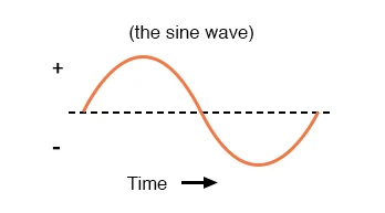
First let's start with 230VAC from the wall. It looks like this:
1757730301314.png

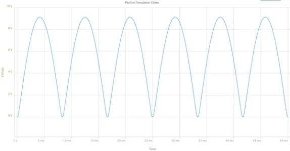
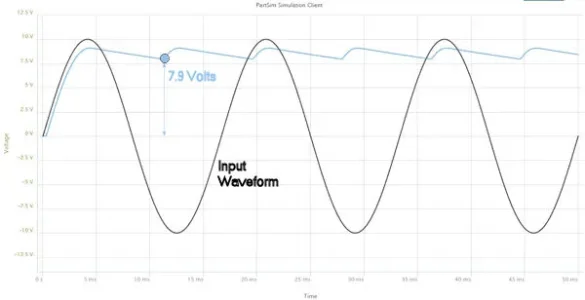
When that's run through a bridge rectifier the part below the center line is moved above the center line so it now looks like this and is twice the frequency:
1757730394173.png

Add a 50uF filter capacitor to it and it looks more like the blue relative to 0V compared to the original AC waveform which swings between -230V and +230V.
1757730442917.webp
The 230VAC is actually what is called the RMS (Root Mean Squared) voltage and the peak voltage of the waveform is 1.414 times larger. So in fact 230VAC becomes 324 Volts DC. That's important because if you want to recreate that AC waveform you need to be able to make the peak voltage. The bigger the capacitor the smoother the waveform.

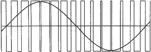
So now what? We have a DC voltage at roughly the peak of the AC voltage. If we switch that voltage on and off at a very high frequency varying the amount of on/off time (and the polarity) and add a combination of inductance (motor winding) and capacitance we end up with the AC waveform again like this superimposed here on the PWM (Pulse Width Modulation):


1757730262774.png

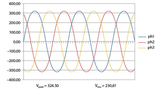
So using the same technique and multiple transistors carefully switching on and off to also change the polarity of the output you now have this with each AC wave delayed by 120 degrees:

1757730896686.png
Change the pulse widths on the DC voltage and the newly generated sine waves can go from 30Hz to 120Hz which means the motor speed also changes.

And that in a nutshell (and oversimplification) is how a VFD works.
 
I would like to add my 42 cents to the discussion on VFDs and how they work.

Excellent explanation John. I'm still of the view that the Sparkys among us already know that and the non-Sparkys dont understand much at all. But maybe I'm being too generous to the Sparkys and too hard on the non-Sparkys.

I taught introductory electronics to first and second year engineers. It was a very rough go. On the other hand, I have a rather high regard for how much our CHMW members know. So I'm kinda keen to know how many of our non sparky metal workers understood it ......
 
As @David says, they should do nicely.

The motor is not VFD rated, but that makes it affordable. Just keep the frequency between 45 and 75 Hz (+/- 25%) for normal operation and you should be fine. A bit lower and higher is ok if you really need it, but I'd avoid full load. That actually matches up well with your decision to double the HP. I don't recommend that - 50% more is enough. But as long as you limit the accell and decell rates and don't try to make huge cuts, you should be ok. Just be aware that you have doubled your motor HP but didn't double the size of your lathe. Take it easy and your lathe should be very happy.

Excellent VFD. I have two just like it. I can help with programming and hookup when you are ready. It's only weakness (that I know of) is lack of external resistive braking. That isn't a big deal with a 2Hp motor. I believe the VFD will provide plenty of braking without it.
thank you,
My train of thought on this is work more with less effort, hence the two HP, the max rpm for my lathe is about 1330 ( need to look again) per the face plate and belt change selections. I'm not trying to create a big machine outa a little one, I just want to have the oomph and energy and slightly improve on what I have; you can run a marathon with a rucksack or you can run a marathon with a fanny pack, am I wrong here?

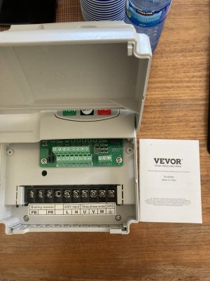
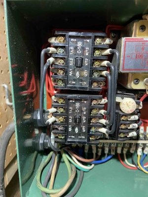
Thank you for the offer, if I get stuck I'll hit u up for help, the link posted earlier (Clough) really nails it, I am looking forward to getting rid of all the wiring octopus from the factory, pic below.

As for the VFD rated motor, should I go back and look for something else, E Motors claimed it was a good combination, in reality a few bucks more (if reasonable) would be a better combination...no?

EDIT, from reading/research this motor is vfd rated, but I'm no expert...cheers
 

Attachments

  • IMG_5275 2.jpg
    IMG_5275 2.jpg
    418.9 KB · Views: 1
Last edited:
Excellent explanation John. I'm still of the view that the Sparkys among us already know that and the non-Sparkys dont understand much at all. But maybe I'm being too generous to the Sparkys and too hard on the non-Sparkys.

I taught introductory electronics to first and second year engineers. It was a very rough go. On the other hand, I have a rather high regard for how much our CHMW members know. So I'm kinda keen to know how many of our non sparky metal workers understood it ......
on that note,
my youngest is off to electronics engineering school in Germany, I have already warned him he's on the payroll/freeroll for my years of diapers, food and lodging, anyone think I'll get a good return on my investment...😉
 
Back
Top