Jswain
Joe
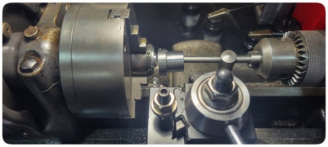
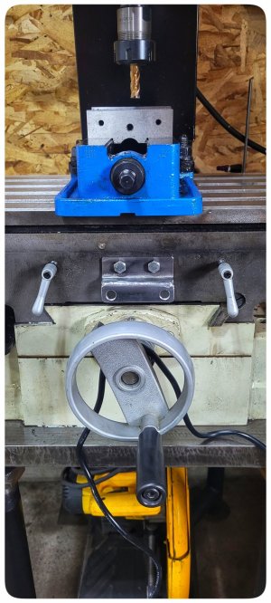
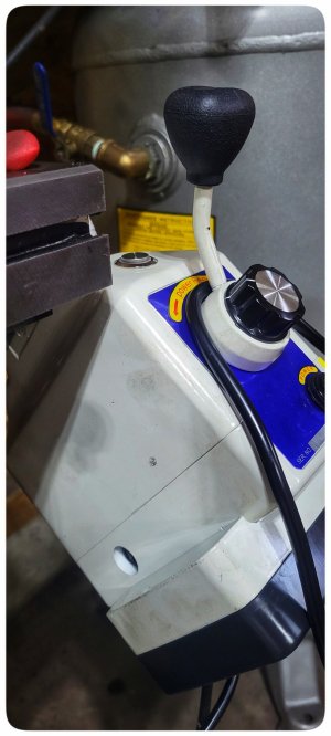
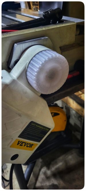
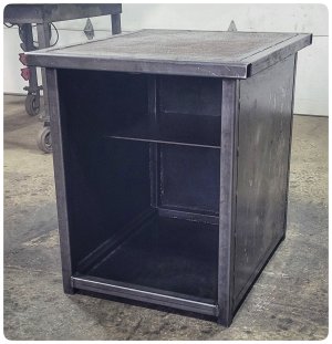
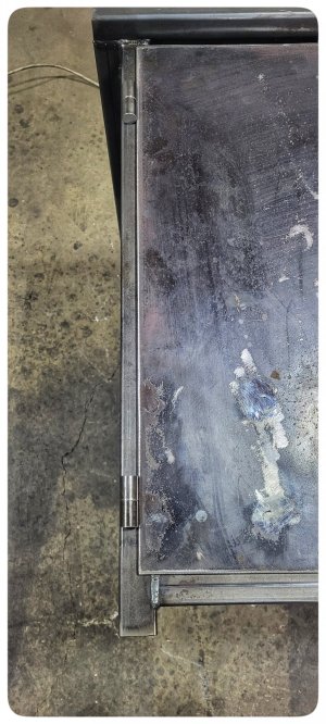
It touches the table in the very corner! I don't think it's stopping it from full travel, but I'm either going to turn the black knob 90 degrees or make a smaller knob. It doesn't seem like the knob is threaded but I didn't try very hard.Boy.... that fwd/rev handle looks crazy close to hitting the table????
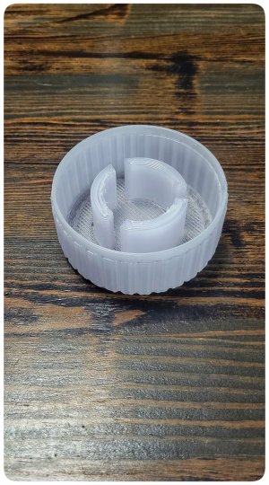
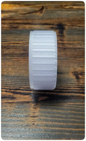
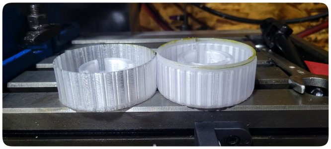
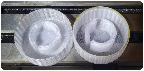
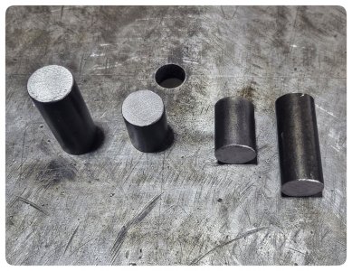
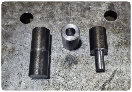
Ask @David_R8 to send you (or publish) his 3D printer file for the end cap to cover the brass gear.
I am going to try and make my own cover as I need all the practise in fusion360 that I can get, but if I fail I may have to ask for an STL file😛