• Scam Alert. Members are reminded to NOT send money to buy anything. Don't buy things remote and have it shipped - go get it yourself, pay in person, and take your equipment with you. Scammers have burned people on this forum. Urgency, secrecy, excuses, selling for friend, newish members, FUD, are RED FLAGS. A video conference call is not adequate assurance. Face to face interactions are required. Please report suspicions to the forum admins. Stay Safe - anyone can get scammed.

JCDammeyer's 42 projects

Over travel switch in series with the limit switch of the direction the Z axis is moving. For me that works with the mechanical NC limit switch and the mechanical switch in the tool setter.

View attachment 74795

Haven't looked into how I'd connect the proximity type switches yet. I have them. They aren't installed.
That's a smart approach. I can likely do something similar
 
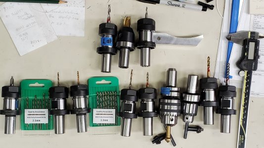
All that discussion on collets had me thinking I'll buy a metric set. Then a quick trip down to the shop and what do you know I had two imperial collets that fit my 2.5mm and 3.3mm drill bits. That means fixed length in the tool table making for faster operations since the Robot Arm has a pretty fixed set of hole sizes and thread tapping. And only a few times I need the chuck.

ProjectTTS.jpg
 
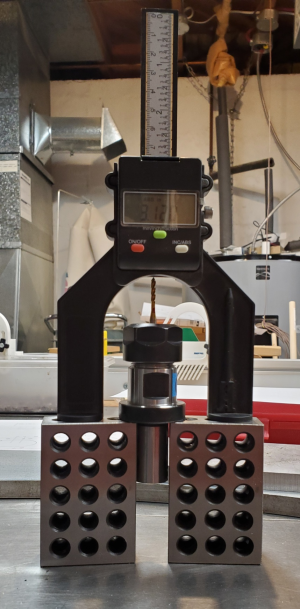
Today I've been working on numbering all my TTS tool holders and cleaning up the tool table so I can create one file for use with CAD/CAM and have the proper lengths in the LinuxCNC tool table. My tool setter is out by about 0.038" when it measures compared to using this:

1766194372106.png
And when I enter the value from this table saw blade height gauge it matches perfectly with the probe so I know I have an issue with the tool setter.

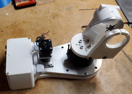
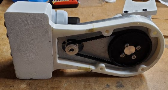
All this so it will be easier to drill and tap holes and mill profiles for the AR3 Robot Arm. Here's a video of the Joint 1 being exercised with my ELS (using the built in stepper driver to keep wiring simple).
Edit: It's only 15 seconds. Not 15 minutes or 15 hours.

 
Last edited:
Does the shoulder of the holder sit tight against the face of the spindle? I know my TTS R8 collet is ground a bit short to be recessed and ensure the shoulder is tight to the spindle nose.
 
One of the interesting things about LinuxCNC is that you can start it from the command line. Now granted... it's Linux. Antiquated PDP-10 do everything from the command line because there's not a lot of memory so even just changing upper case to lower case is too expensive.

Anyway. With the command line window available diagnostics can be sent there during the processing of G-Code programs.

Code:
%
(measure_toolsetter_inch v1.3)
(PROBEOPEN toolsetterlog.txt)
G20               (Switch to Inch units)
M5                (Turn spindle off)
M61 Q99           (Select tool 99 so probe will work)
G49               (Cancel tool length offset)
G92.1             (Cancel and reset G92 offsets)
G59.3             (switch to G59.3 coordinate system)
G91               (Incremental mode)
#<old_result> = #5383
G38.2 Z-.5 F25    (Measure fine  var=5063)
G1 Z0.1
G38.2 Z-.2 F1     (Measure fine  var=5063)
G10 L20 P9 Z.0000 (Set Coordinate System)
G4 P.5            (Dwell)
G0 Z1             (Move Z up 1 inch)
#<touch_result> = #5383
#<difference> = [#<old_result>-#<touch_result>]
(PRINT, New Z Offset = #<touch_result>, difference is #<difference>)
G54               (Switch to G54 coordinate system)
G90               (Switch to absolute mode)
M61 Q0
G49
(PROBECLOSE)
M2
%

To measure the height of the tool setter is important when trying to dynamically measure tools. Even if just to insert the tool length into the tool table. In the above G-Code program I added some print statements to look at the repeatability of probing the tool setter.

What I found was that repeating this G-Code program resulted in values that only differed by about 0.0005" so overall I could rely on the values. (be nicer with a z axis ball screw but that's the future).

Originally when I got the new tool setter I first moved the knee up until the quill touched a 1-2-3 block set to show 2". I recorded the machine co-ordinates and then moved over and moved the knee up until the quill registration face tripped the tool setter.

That machine co-ordinate along with the 2" 1-2-3 block gave me the trip point and therefore the height of the tool setter. I recorded that into the machine .ini file. Problem was the value didn't match what the above code generated, likely due to deceleration time after the switch trips compared to jogging 0.001" at a time.

Once I changed the .ini file to use value as determined by the above G-Code and restarted LinuxCNC a tool height measurement matched the table saw blade height tool within 0.001" or so.

I think I have the problem solved. I can run the ToolMeasure.ngc G-Code and the value written into the tool table is now accurate.

Of course the next time I try this there will be something else screwed up. 😕
 
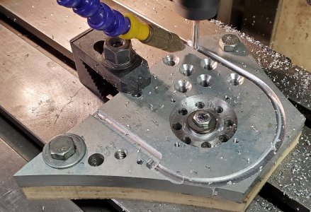
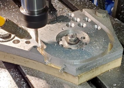
One day I might actually machine something that looks pretty. Since there was non-clamped areas around the part that might come loose the wrong way I made the final cleanup pass have pads thinking that last bit was really thin anyway.

Well each time the tool went down after lifting up and moving further to create the tab the tool bit flexed and cut vertical bumps. Turns out it was thicker than I thought. When will I learn?

Some cleanup and holes in the edges and I can score the loss of only one 4mm spiral tap in this piece.

FinalCutWithTabs.jpg
 
So I'm just about ready to cut the next part for the AR3 Robot Arm. This time I'll do the perimeter and the larger hole with a 1/2" 2 flute mill rather than the 6mm to avoid the bending of the cutter.

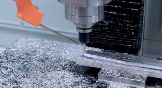
Found this video. Some good information.
 
Found this video. Some good information.

I just couldn't watch the whole thing, but there was value in what I did see.

I never heard of the rule of only cutting as deep as you are wide. But it makes some sense. And I love the integrated air nozzle to reduce recutting chips. Although, I don't really want to run the air compressor.

Screenshot_20260122_084946_Chrome.jpg

But I have no idea what he means about long curly chips. That's a lathe thing, not a milling thing.

Might need to ask @SkookumRob what he thinks and has for hobbiests like most of us.
 
I just couldn't watch the whole thing, but there was value in what I did see.

I never heard of the rule of only cutting as deep as you are wide. But it makes some sense. And I love the integrated air nozzle to reduce recutting chips. Although, I don't really want to run the air compressor.

View attachment 76882

But I have no idea what he means about long curly chips. That's a lathe thing, not a milling thing.

Might need to ask @SkookumRob what he thinks and has for hobbiests like most of us.
Yeah. Long curly chips went over my head too. As shown in the photo a few postings back my air nozzle is integrated with the mill so it can be adjust to blow away the chips which makes a big difference.

The other interesting suggestion was when cutting a perimeter or an internal hole to cut two slots rather than just one for each depth pass. That results in a wider slot for chip clearance. I'm thinking if cutting a 60mm hole with a 10mm cutter normally the path is following a 50mm circle.

Instead cut a 45mm circle at 5mm deep and then cut the second 50mm circle at 5mm deep. And so on. A bit more metal gets turned into chips but the path for the chips is wider and the important cut is only on the important edge.

If that all makes sense.
 
Back
Top