• Scam Alert. Members are reminded to NOT send money to buy anything. Don't buy things remote and have it shipped - go get it yourself, pay in person, and take your equipment with you. Scammers have burned people on this forum. Urgency, secrecy, excuses, selling for friend, newish members, FUD, are RED FLAGS. A video conference call is not adequate assurance. Face to face interactions are required. Please report suspicions to the forum admins. Stay Safe - anyone can get scammed.

JCDammeyer's 42 projects

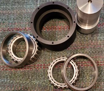
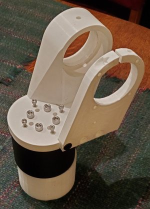
And in keeping with the thread subject before this goes too far off the deep end (ha ha) I reprinted the J1 Turret Hub overnight. This time with support for the PLA-CF and door half open. Also enlarged the outer bearing diameter sections by 0.25mm. Now they are a nice smooth fit.
 

Attachments

  • J1_TurretBearings.jpg
    J1_TurretBearings.jpg
    159.8 KB · Views: 0
  • J1_TurretHousing.jpg
    J1_TurretHousing.jpg
    118.5 KB · Views: 0
Ohhh, a robot arm. And the AR3. I too have been interested in that (now AR4) but fortunately for me the price of entry has been just a touch too high for me to jump as I really have no need. Now if I could convince work that they could use a cobot and that this would be a great intro to using them...
 
Ohhh, a robot arm. And the AR3. I too have been interested in that (now AR4) but fortunately for me the price of entry has been just a touch too high for me to jump as I really have no need. Now if I could convince work that they could use a cobot and that this would be a great intro to using them...
I bought all the parts for the AR3 but have been slow building it. Meanwhile he came out with the AR4 with different encoders etc. It's backwards compatible so not a big deal but with $400 or so invested in everything I don't really want to redo it as an AR4.

I wanted to make it a tool changer and part swapper for automating mill operations. And because I think a robot arm is just plain cool!

It was 2.5 years ago that I did all the drawings from his or from the STL files that a friend JoeMac turned into STEP files. All the parts came in. Even made some patterns for the castings to keep the cost of metal down. Then the family disaster so no interest in doing anything for 2 years.

Anyway. Ran into another problem... Never ends... Although I should expect 42 problems I guess.

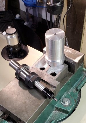
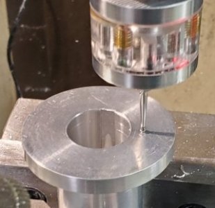
Used my touch probe with LinuxCNC to find the center of the Joint 1 spindle so I could drill the 8 hole pattern. Probe goes over to the left and finds the edge. The distance it moves from centre is supposed to be just over the radius of the part so I set it at 1".

All went well. Moves over, goes down, comes back, touches, moves off and comes in slowly for second touch. Then lifts up and it's supposed to move 2x that radius value (2") plus Clearance x 2 (0.2" x 2= 0.4") to the other side of the round piece. Doesn't go 2x. Goes half the distance. Something is hooped in the G-Code. Don't want to try and fix it at the moment.

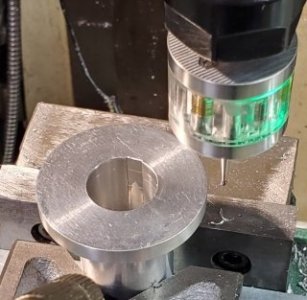
Instead I pulled out the LED based touch probe and used my Shumatech DRO-350 to find the centre and then store the locations for 8 holes. Worked through that manually and now have 8 dimples in a circle that look right.

Glad I kept the manual feature and DRO.

 
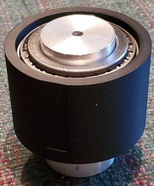
It's done on this side. Still have to do the other side but just had to attach the plastic models to see how the taper bearing loading all worked.

So somehow although I checked it twice the CAD/CAM software was naughty, not nice. So when I went to chamfer the drilled holes somehow the depth was not what I had entered. Or maybe my finger slipped. Anyway the first hole was supposed just have the sharp edge removed and instead it went into countersink mode. A bit of G-Code editing and the other seven were fine.

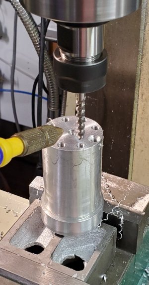
Then the power tapping. This picture is after the last hole was tapped 6 x 1.0mm. So cool to watch it tapping automatically.

TappingHoles.jpg

The 4 small screws will be set screws to load the bearing. The 8 (4 installed) 6mm bolts fasten the plate. The plate will be milled out of Aluminum plate. Maybe this weekend.

J1-SpindleTrialFit.jpg
 
John,
You are experiencing ‘Machine Development’.
It is a great benefit to see how machinery is used at the point of installation.

As a process designer the KEY thing that was missing . . . would be feedback from the end users.

For a few years I had the benefit of production plants feeding me information about ‘point of use’ reports that could be recorded and used in PLM documentation to improve the industrial equipment.
Improvements can be derived from several viewpoints.
 
Yes. It's frustrating that people design stuff. Then post it maybe even with full source code and then move on to other things. When they do post an upgrade (if they post one) often they change all sorts of things "To enhance our user experience".

Before I drill the 4 holes for the toothed pulley on the other side of the spindle I'm going to try and figure out why the outside of a circle probing doesn't work right.
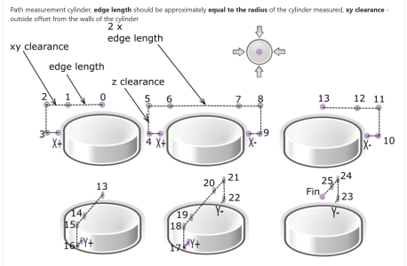
From the user instructions:

1764977885863.png

The edge length is set to 0.9" for the spindle that has a 1.75" diameter. Starting approximately at the centre it moves to point 2 and then down and then in at point 3. All good. Moves to point 4, to point 5 and then not to point 7.

It used to work...
 
Maybe your probe experiencing a loss of position.
Is there a ‘static’ influence when it moves from point 5 ?
 
Maybe your probe experiencing a loss of position.
Is there a ‘static’ influence when it moves from point 5 ?
Nope. It's python code that runs G-Code.

Python:
        # Start psng_xplus.ngc
        if self.ocode("o<psng_xplus> call") == -1:
            return
        # Calculate X result
        a = self.probed_position_with_offsets()
        xpres = float(a[0]) + 0.5 * self.halcomp["ps_probe_diam"]

        # move Z to start point up
        if self.z_clearance_up() == -1:
            return

        # move X + 2 edge_length + 2 xy_clearance
        tmpx = 2 * (self.halcomp["ps_edge_length"] + self.halcomp["ps_xy_clearance"])
        s = """G91
        G1 X%f
        G90""" % (
            tmpx
        )
        if self.gcode(s) == -1:
            return

The code adds the two distances, multiplies by 2 and then uses that for the X relative distance.
 
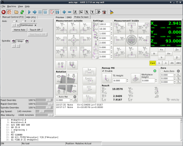
This is the glade probe screen used with python code:

1764981957486.png

The settings column has the distances or speeds to move. Hover over the little icon beside it and it will tell you the name of the parameter. In this case the important parameter is Edge Length. If I click on the up/down keys the values increment by 1.0. Originally this was a metric only program and other Linux People have said it's too difficult to make something that works in either units mode. (They should look at my ELS code to see how it's done).

Anyway. I set the value to 0.500 which is 1/2" now. Then I closed down and restarted Linux. Hmmm. It was back at 1.000. I changed it to 0.500 and hit enter. Then tried the probing operation. Worked perfectly.

Changed it to 1.0 which means it should go, from the center position, to -1.250" which is edge_length plus xy_clearance. It didn't. It didn't go quite that far and then after probing the one side went back the other way and stopped just past centre and went down. And probe tripped error occurred.

So something in the Glade+Python environment is broken. More later on this...
 
So something in the Glade+Python environment is broken. More later on this...
I hope you figure it out. I feel that issues like this cost me 2 touch probes before I gave up on Linuxcnc for probing. Now that I'm down to only the lathe for true Linuxcnc I don't need it on that, but would still like to see the solution if I ever get back to Linuxcnc on a mill.
 
I hope you figure it out. I feel that issues like this cost me 2 touch probes before I gave up on Linuxcnc for probing. Now that I'm down to only the lathe for true Linuxcnc I don't need it on that, but would still like to see the solution if I ever get back to Linuxcnc on a mill.
This is all about Glade and Python and the crap environment they create. The type of error that is happening can't happen with Delphi.
It's something to do with parsing the Glade fields and returning the wrong result. A tab to leave the field also leaves it with what I entered. But it doesn't seem to stick. A CR does save it but not so it's used. I have to shut down LinuxCNC and restart it. And even then the screen doesn't show the right value.

I had entered 0.5. It showed 1.000. I then changed it to 0.500 (both zeroes) and hit enter. Try the probe and this time it works. Set it to 1.000 and it does a strange distance.
Digging further into the Glade image code I see this:
Python:
  <object class="GtkAdjustment" id="adj_edge_length">
    <property name="upper">1000</property>
    <property name="step_increment">1</property>
    <property name="page_increment">10</property>
  </object>

Notice the upper limit is 1000 which is fine for millimeters but pretty crappy for inches. I'm going to guess that somehow this limit is causing faults when the 2x the edge_length is > 1.000".
Now I see why the increment is also by 1 rather than 0.1 for example (or even 0.05)

I'll change these values and reboot and see what happens.
 
Changing to 0.05 and 1 for the increments works. The arrow keys now adjust the values and in the range of 0.450 to 0.600 the centering operation works. The upper limit was set to 10000 so that didn't make any difference.

However setting the edge_length to 1.000 and even using the increment and decrement arrow buttons to adjust the value doesn't matter. The initial probe is distance is correct but the math fails. There's another restriction somewhere else.

At least at the moment I can find the center of the 1" diameter end of the spindle and drill/tap the 4 pulley mounting holes. Not quite ready to ask on the LinuxCNC group just yet.
 
Interesting. I managed to get a print statement into the python program.
Python:
       # move X + 2 edge_length + 2 xy_clearance
        tmpx = 2 * (self.halcomp["ps_edge_length"] + self.halcomp["ps_xy_clearance"])
        s = """G91
        G1 X%f
        G90""" % (
            tmpx
        )
        print s

Oddly it showed up on the console like this:

G91
G1 X2.400000
G90


And the probe goes down too soon as in this photo.

IncorrectPosition.jpg

Where if I go back to where it started with the jog X button after moving it up again and then issue a
G91
G1 X2.4


It ends up where it should
CorrectPosition.jpg

I've asked for help on the LinuxCNC mailing list.
 
Last edited:
No help yet from the mailing list but as I dove deeper into the Python and glade code I found two issues. The feed across is supposed to use an INI file parameter RAPID_SPEED. Like this which I simulated in Thonny Python on my PC:

Python:
s = "G91\nG1 X2.400000\nG90"
print( s )
for l in s.split("\n"):
    # Search for G1 followed by a space, otherwise we'll catch G10 too.
    if "G1 " in l:
        l += " F#<_ini[TOOLSENSOR]RAPID_SPEED>"
    print( l )

The output from this on my PC is:
Code:
G91
G1 X2.400000
G90
G91
G1 X2.400000 F#<_ini[TOOLSENSOR]RAPID_SPEED>
G90

However the F#<_ini[TOOLSENSOR]RAPID_SPEED> does not show up in the LinuxCNC console output so the system didn't use the new F20 speed I had changed to.

Why F20? Well I figured it this was a time delay problem then moving twice as fast from F10 to F20 would then not time out. It took a few tries doing other things before the F20 did start working in the probe functions. And the fault went away.

So next search for the issue with the linux command (or python) wait_complete because it clearly wasn't waiting for completion of the move across before it went downwards.

The right question to google returned this thread:

I'm going to try the timeout issue fix from the posting from "natester" on 20OCT2024.
 
OK. For now problem solved. The real solution for the going down at the wrong spot is the self.command.wait_complete() function which has a default (hidden) parameter of 5 seconds. Which is why at 10 ipm it stops before it's reached the 2.4" position. Change the speed to 20 ipm and it works. Change the code so the wait_complete(600) puts in a 10 minute delay before it stops and it works with the 10 ipm. (Actually works with a delay of 20 seconds).

There is a thread on that which addresses my problem but because the subject is wait complete and not the actual probing I didn't find that link right away.
 
Did you air cut first just a little bit? For scary programs I usually have it run the code so that the lowest move will still be above the material, and I can get a feel for how its going to go. Can't always do that if its a really long program, but helps build confidence that Z moves are ok.
 
Back
Top