• Scam Alert. Members are reminded to NOT send money to buy anything. Don't buy things remote and have it shipped - go get it yourself, pay in person, and take your equipment with you. Scammers have burned people on this forum. Urgency, secrecy, excuses, selling for friend, newish members, FUD, are RED FLAGS. A video conference call is not adequate assurance. Face to face interactions are required. Please report suspicions to the forum admins. Stay Safe - anyone can get scammed.

JCDammeyer's 42 projects

Did you air cut first just a little bit? For scary programs I usually have it run the code so that the lowest move will still be above the material, and I can get a feel for how its going to go. Can't always do that if its a really long program, but helps build confidence that Z moves are ok.
I'm about to do the first step which will verify things. Centre drilling all the locations for holes.

And I thought I had verified all the depths but the CAM program decided that the surface of the hole was after the recess had been milled so it was still going at full tilt 120ipm to reach the 0.1" point above the plate before doing the next hole. The last time I checked the G-Code it didn't do that so probably the process of making sure I was avoiding the clamps it did something and I didn't double check.

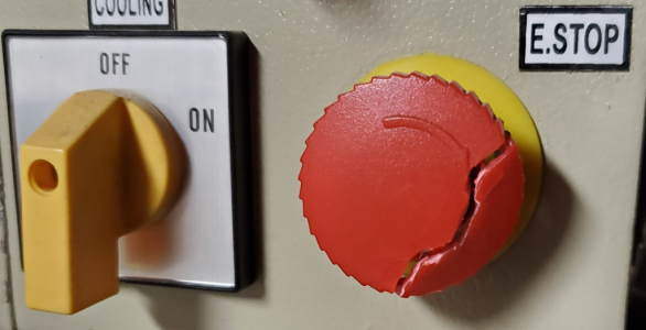
Broke the centre drill. I was even doing a video with my phone but as it made the large noise I didn't really catch it in detail because filming was forgotten as my hand hit the ESTOP.

What I didn't realize is that a piece of the drill broke off inside the aluminum. So when I started it all over again this time not speeding into the hole it still snapped the centre drill again because it hit the HSS of the original. Took a magnet (should have done that the first time) and sure enough there's something in there.

Easy solution would be to take a 4mm carbide end mill to remove it. Or even carbide drill?
 
Can you do a little circular interpolation on that hole? 4mm end mill would do it but better to use it like an end mill and cut from the side and not plunge in. Don't want a layer cake of HSS and carbide on aluminum.
Carbide drill can do it too, but I find it sketchy the few times I've tried. If it doesn't cut, it will deflect and break if its a small drill. You'd need to use the biggest the hole will allow.

Good luck, sucks to start a part like that. Hopefully it gets better.
 
Can you do a little circular interpolation on that hole? 4mm end mill would do it but better to use it like an end mill and cut from the side and not plunge in. Don't want a layer cake of HSS and carbide on aluminum.
Carbide drill can do it too, but I find it sketchy the few times I've tried. If it doesn't cut, it will deflect and break if its a small drill. You'd need to use the biggest the hole will allow.

Good luck, sucks to start a part like that. Hopefully it gets better.
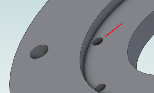
It's this hole right here. Quite possible the broken part doesn't even go down that far or if it does just barely. The target surface is 4mm down. The centre drill part is less than 4mm diameter but the tapered part of the drill may also be stuck in there above the expected surface.

And truthfully it's not likely a real issue if I never even used that hole. The amount of stress won't be that high. But I'm upset. I don't have any other stock that that this piece could fit on. First step is to acquire a carbide end mill to remove the garbage now in the hole.

1765245829707.png
 
It's this hole right here. Quite possible the broken part doesn't even go down that far or if it does just barely. The target surface is 4mm down. The centre drill part is less than 4mm diameter but the tapered part of the drill may also be stuck in there above the expected surface.

And truthfully it's not likely a real issue if I never even used that hole. The amount of stress won't be that high. But I'm upset. I don't have any other stock that that this piece could fit on. First step is to acquire a carbide end mill to remove the garbage now in the hole.

View attachment 74452
What are the stock dimensions?
 
But I'm upset. I don't have any other stock that that this piece could fit on. First step is to acquire a carbide end mill to remove the garbage now in the hole.

Hey John, if you don't have enough stock to make another one, why don't you just plug all the holes and then clock it 15 degrees or so or whatever makes sense.

I know that isn't ideal, but it would get you going again.
 
Hey John, if you don't have enough stock to make another one, why don't you just plug all the holes and then clock it 15 degrees or so or whatever makes sense.

I know that isn't ideal, but it would get you going again.
Not wide enough to turn. I have a 1/4" carbide router bit that I could plunge down 4mm and then take a look to see if there's any more of the drill bit below that.
 
1/4" carbide router bit cleaned out the hole. Then I ran the program again and the final holes resulted in a scratch across the plate from hole to hole. I did fix that but forgot to update the machine file from the USB drive. Crap. No problem. That gets milled away later anyway.

Then I discovered my probe was no longer registering the correct work height.... oh yes. I remember. I bumped the body which pressed the whole thing further into the TTS collet holder.

Go through the whole probe measuring process and somewhere a parameter has been screwed up in the linuxvars file. Oops. That's the one thing that I didn't write down in my notes on how to set this all up. And I remember it was giving me trouble. Just have to relearn what I have forgotten.
 
Well. Status update. I found a document I wrote from November 2023 before our family crisis. It wasn't complete but it did help me restart the process of adjusting things. Was able to measure tools again.

Drilled all the holes (3.2, 4.0 and 4.5mm) However, putting a longer 8mm drill bit in the 3/8" drill chuck and watching it measure and then head straight down into the tool setter shattering the drill bit and destroying the tool setter was not a happy moment. Changed to a letter O drill and did a manual measure and entered that value into the tool table since I no longer have a tool setter. Holes are done.

And using the Machinist Toolbox to calculate milling speeds ended up being a disaster.; possibly due to the machine backlash. For a 6mm 2 flute HSS end mill into 6061 the speed of 150 FPM calculates out to 2425 RPM and just over 25 IPM. My axial depth of cut wasn't close to the max 0.2".

Instead I set it to run 2500 RPM and 13 IPM and 11 IPM. Well after the cutter shattered I decided maybe that was too fast. Dropped it down to more like 5 IPM and finished milling out the two holes although the surface finish on the first part of the first hole was kind of bad. I think for that speed of cutting and RPM that the end mill was actually flexing since it protruded a fair amount. Those first two levels have the hole larger than when I slowed down and finished.
 
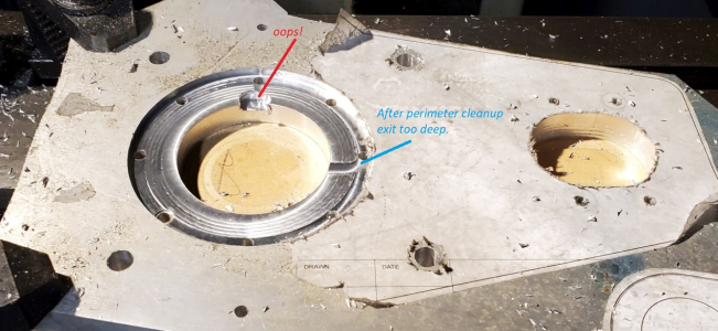
I set the CAM to create a G-code file that did a nice smooth cut around the perimeter of the recess as it was 1mm too small in diameter. Given the tolerance setting that made sense. I also set it for exactly 4mm deep but with the backlash and imperfections in the mill it left a mark a few tenths deep during the circle and exit.
So I thought. Just create a G-Code program to just clean up the bottom of the recess. Looked great on the screen. Should have checked the Z value in the G-Code. For some reason it didn't have the Z value I expected.

Went back to the CAM software. Regenerated the G-Code. It had the correct 4mm depth. Go figure.

Ah well. Once the unit is assembled this won't show. Just that hidden oops...

1765349759290.png
 
Last edited:
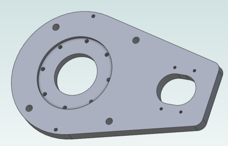
Maybe I'm just too stuck in the past, but how is all this CNC-ing faster than using a boring head? Align mill, cut the centre hole as big as possible with a hole saw, bore to finished size, bore outer recess, lay out bolt holes, drill & tap. It's aluminum, a carbide boring bar goes through that stuff like butter. That's how I occasionally make pipe flanges and modify valve bodies using my mill, and I'm a hack at best.
 
Maybe I'm just too stuck in the past, but how is all this CNC-ing faster than using a boring head? Align mill, cut the centre hole as big as possible with a hole saw, bore to finished size, bore outer recess, lay out bolt holes, drill & tap. It's aluminum, a carbide boring bar goes through that stuff like butter. That's how I occasionally make pipe flanges and modify valve bodies using my mill, and I'm a hack at best.
You are right. Not even close to being faster other than cutting out the profile shape perhaps.

In fact, because the first end mill broke cutting out the round centre hole I did finish it off at a slower milling speed. It we pretty obvious when I was done that the reason it broke was the travel speed verses RPM. I think it flexed enough that it definitely did the first one and a half passes with that wobble making the hole larger. In the end I used a boring tool and cleaned up the inside of the hole which is now 4mm larger. Doesn't matter in this case.

I didn't have a tool on hand to use with the boring tool to cut the larger recess which centres the turret holding bearings. In the past I've mounted that sort of thing on the lathe face plate but it's too large so that wasn't an option either since it would require a 12" lathe. Maybe the recess isn't needed but I'm trying to follow the plans.

1765389006264.png

The layout holes could have easily been done with the guided bolt circle feature in the Shumatech DRO-350 as well as positioning for all the others. And yes overall it would have been faster.

However, if the MIG welding course at Camosun College costs over $1k for 10 classes I wonder what the CAD/CAM courses for machines I can't afford to buy would cost. Likely way more than the bits I've broken and so I think also more time than I've put into it all.

After this project is done it's clear I'm going to need to change to Ball Screws on the mill and a different spindle drive mechanism. The rattle from the splines is annoying enough to have to wear ear protectors. OTOH, when the compressor cuts in I don't jump.......

No matter which way we look at it I think education is expensive.
 
I didn't have a tool on hand to use with the boring tool to cut the larger recess which centres the turret holding bearings. In the past I've mounted that sort of thing on the lathe face plate but it's too large so that wasn't an option either since it would require a 12" lathe. Maybe the recess isn't needed but I'm trying to follow the plans.
rotary table, and milling it?

I see every experience as a learning opportunity. This project, along with these messy issues, hopefully won't discourage you too much. I am vicariously learning about CNC stuff from your travails!
 
rotary table, and milling it?

I see every experience as a learning opportunity. This project, along with these messy issues, hopefully won't discourage you too much. I am vicariously learning about CNC stuff from your travails!
Actually you and @Susquatch are correct. Since I spray glued the drawing onto the plate to be able to orient it to fit on the mill (just barely) drilling the first hole with a hole saw and then using the boring tool to clean it up to dimension would have been the best way.
That second hole could be clean out with a hole saw first and then a larger mill to clean the edges and provide a radius. It's really just a slot to provide clearance for the motor and pulley for belt tightening.

1765393831726.png

Once that first hole is to spec and the holes all drilled using the DRO for positioning and just hand drilling with the quill I could remove it from the sacrificial MDF and mount on the rotary table.

With that I could turn table to create the recess and also the large arc on the perimeter. Then leave it at the right angle and cut the side. Rotate to opposite angle and cut the other side. The bottom end just at 90. The rounding of the two bottom corners more of an issue....
 
Its good to try out and learn all the CNC functions on simple, unimportant parts, much harder (or impossible) to learn without doing.
I think hitting snags makes the lessons stick a bit better, versus it just going right the first time. In those cases where it all goes well the first time, you are very likely just kicking the learning down the road, usually on a part that is expensive / rare / important. Better now than then.
 
Back
Top