Nope. Unless they started opening on weekends again :-(I'll have to check metal supermarket tomorrow morning I guess
-
Scam Alert. Members are reminded to NOT send money to buy anything. Don't buy things remote and have it shipped - go get it yourself, pay in person, and take your equipment with you. Scammers have burned people on this forum. Urgency, secrecy, excuses, selling for friend, newish members, FUD, are RED FLAGS. A video conference call is not adequate assurance. Face to face interactions are required. Please report suspicions to the forum admins. Stay Safe - anyone can get scammed.
-
Several Regions have held meetups already, but others are being planned or are evaluating the interest. The Calgary Area Meetup is set for Saturday July 12th at 10am. The signup thread is here! Arbutus has also explored interest in a Fraser Valley meetup but it seems members either missed his thread or had other plans. Let him know if you are interested in a meetup later in the year by posting here! Slowpoke is trying to pull together an Ottawa area meetup later this summer. No date has been selected yet, so let him know if you are interested here! We are not aware of any other meetups being planned this year. If you are interested in doing something in your area, let everyone know and make it happen! Meetups are a great way to make new machining friends and get hands on help in your area. Don’t be shy, sign up and come, or plan your own meetup!
You are using an out of date browser. It may not display this or other websites correctly.
You should upgrade or use an alternative browser.
You should upgrade or use an alternative browser.
G3616 Conversion.
- Thread starter jcdammeyer
- Start date
Not really a big deal. Unlike a servo that I can switch over to constant torque mode I have to be able to detect that the stepper motor has stalled with a specific power setting. If the stepper driver has resistors for setting current then it's pretty easy to use a relay to switch them based on the motor direction. 18 ft-lb for tighten. 20 ft-lb for loosen.Nope. Unless they started opening on weekends again :-(
But most of the drivers I have use switches to set current. There is one where I think I can put a relay across the dip switch. But I also need to interface to a quadrature encoder so I can tell when it's stopped turning. Quadrature so if it's vibrating around the sensor edge that we also detect that.
I could use 1 PPR on the motor, which if stepping at say 10kHz with 2000 steps/rev I should see a pulse every 0.2 seconds. So if no pulse occurs after that time I will know it's stalled. Since it stalled at a higher speed and torque falls off on a stepper for higher speeds it's likely it will just buzz once stalled at that lower torque value. I could then step very slowly for another 1/4 turn (after reduction drive) to firmly tighten it.
To loosen, set higher current into motor, turn slowly for two turns. Then speed up if trying to remove R8.
This would be so much easier with a servo motor compared to a stepper.
No. I don't have 5mm metric in stock. I have lots of Philips Pan head and the bolt diameter is large enough to clear the socket. Plus I might still mount a flat slotted encoder disk there instead of mounting an encoder on the back of the stepper motor.no recess to use socket-head cap screws?
I have a couple of US Digital encoders I pulled off my DC brushed servos because they were very unreliable. Switched to CUI for those motors. But likely for what I want on the draw bar it would be adequate. But making up an aluminum disk with slots using the slitting saw and indexing on the rotary table is pretty easy.
Or even just a disk with a ring of small holes which I can make LinuxCNC do without a rotary table.
Hence no socket head screw capability.
Attachments
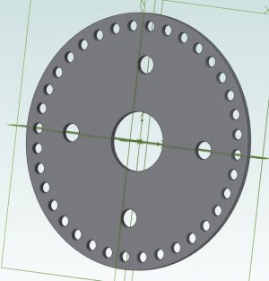
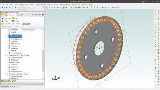
And just for general interest. The 3D parametric CAD drawing took less than 10 minutes. The CAM using AlibreCAM took about 25 minutes which includes generating and zipping the G-Code .ngc files.
I'm not suggesting anyone use the files but if you are interested in what I did.
How I would use them would be to:
1. 0.042" aluminum sheet a bit larger than the diameter placed onto scrap plywood or MDF and held in the corners. Ensure that the center point sits over a T-Slot.
2. Run the G-Code that cuts out the middle hole.
3. Hand drill through the plywood and with a large fender washer and a bolt anchor down the middle.
4. Next run the G-Code that does the center drilling for the mount holes and encoder holes.
5. Run the G-Code that does the 4 mounting holes.
6. Screw self tapping screws into the wood through the 5mm mount holes.
7. Run the G-Code to drill the encoder holes.
8. Finally run the G-Code to cut out the outer perimeter.
9. Remove the outer clamps, screws and bolt.
10. use a deburring tool to clean the perimeter if the edge is ragged. Same with the 14mm center hole.
11. Depending on the state of the encoder holes deburr from the rear with a hand tool.
12. Mount to adapter.
There. A 12 step program...
Attachments
I found in the drawings/XAxis folder all sorts of drawings and photos I had done a few years ago. Working with ordering parts from AliExpress for the Robot Arm I realized I should get after getting ball screws. The thing that put that project #42 on hold was not knowing whether to use a 16mm, 20mm or replacement 2505 sized ball screw to replace the 1" ACME 0.2" pitch screw.
I had a photo of the screw nut and where it went when I had the table off a few years ago.


But I really couldn't tell from those pictures whether the much larger ball nut and holder would fit. So first step is remove the RH side plate, wind the lead screw all the way over so the edge of the table lined up with the frame section in the photo above. Dangled a square over to measure to the screw center line.

Well lots of measurements. Sketches, then CAD drawings and finally taking the original ACME screw and nut assembly drawing I did in 2017 and adding it to the two parts I drew today.
Here's a perspective view.

So similar end view with the ACME screw centered on the X axis.

Looks like there will be plenty of room for a larger ball nut holder. Why not just go with a 16mm screw? Well the pulleys and bearings and spacers etc are all sized for the current 1" ACME screw. The cost of a 25mm over a16mm isn't that high and the rounded ends then match all my bearings and the pulley.
All I need to do is cast new end plates with the hub in line with the new ball screw center line. Easy to do since it was a two part pattern. Just move the hole up and use some wax to plug the old one.

All for now. Time to download the 1" double ball nut step file and model it with the parts done here.
I had a photo of the screw nut and where it went when I had the table off a few years ago.
But I really couldn't tell from those pictures whether the much larger ball nut and holder would fit. So first step is remove the RH side plate, wind the lead screw all the way over so the edge of the table lined up with the frame section in the photo above. Dangled a square over to measure to the screw center line.
Well lots of measurements. Sketches, then CAD drawings and finally taking the original ACME screw and nut assembly drawing I did in 2017 and adding it to the two parts I drew today.
Here's a perspective view.
So similar end view with the ACME screw centered on the X axis.
Looks like there will be plenty of room for a larger ball nut holder. Why not just go with a 16mm screw? Well the pulleys and bearings and spacers etc are all sized for the current 1" ACME screw. The cost of a 25mm over a16mm isn't that high and the rounded ends then match all my bearings and the pulley.
All I need to do is cast new end plates with the hub in line with the new ball screw center line. Easy to do since it was a two part pattern. Just move the hole up and use some wax to plug the old one.
All for now. Time to download the 1" double ball nut step file and model it with the parts done here.
Took the model of the 25mm ball screw I did a couple of years ago. Now that I have the table assembly modeled I created a ball nut holder and with some bevels on the holder.

I will have to cast new end plates and come up with a better method of locating the holes. Unfortunately the Chinese builders didn't put them in symmetrical locations. On the RHS the set is even turned CW a tad so the top of the holder isn't level.
I suspect they had some sort of jig that held the ends of the ACME screws so it was parallel in the two dimensions to the table and then they just pressed the end plates and used a centering punch to set where the holes go. That a plate pivoted slightly wasn't important...
Former Member
Guest
Going down this route soon.I found in the drawings/XAxis folder all sorts of drawings and photos I had done a few years ago. Working with ordering parts from AliExpress for the Robot Arm I realized I should get after getting ball screws. The thing that put that project #42 on hold was not knowing whether to use a 16mm, 20mm or replacement 2505 sized ball screw to replace the 1" ACME 0.2" pitch screw.
I had a photo of the screw nut and where it went when I had the table off a few years ago.
View attachment 30602
View attachment 30603
But I really couldn't tell from those pictures whether the much larger ball nut and holder would fit. So first step is remove the RH side plate, wind the lead screw all the way over so the edge of the table lined up with the frame section in the photo above. Dangled a square over to measure to the screw center line.
View attachment 30604
Well lots of measurements. Sketches, then CAD drawings and finally taking the original ACME screw and nut assembly drawing I did in 2017 and adding it to the two parts I drew today.
Here's a perspective view.
View attachment 30607
So similar end view with the ACME screw centered on the X axis.
View attachment 30605
Looks like there will be plenty of room for a larger ball nut holder. Why not just go with a 16mm screw? Well the pulleys and bearings and spacers etc are all sized for the current 1" ACME screw. The cost of a 25mm over a16mm isn't that high and the rounded ends then match all my bearings and the pulley.
All I need to do is cast new end plates with the hub in line with the new ball screw center line. Easy to do since it was a two part pattern. Just move the hole up and use some wax to plug the old one.
View attachment 30608
All for now. Time to download the 1" double ball nut step file and model it with the parts done here.
I'm finding it invaluable this time to do all the CAD up front. To make sure things fit. I know on the island if the mill is disabled there are a few people close by who can make some chips if I make a mistake. But I'd rather not have the mill that disabled.Going down this route soon.
Former Member
Guest
For me the plan is some maintenance to see what wear hard CNC is causing and plan mitigation. Measure up and design mounts for the ballscrews. Assemble and continue work will setting up for next retrofit (without glitches one hopes).I'm finding it invaluable this time to do all the CAD up front. To make sure things fit. I know on the island if the mill is disabled there are a few people close by who can make some chips if I make a mistake. But I'd rather not have the mill that disabled.
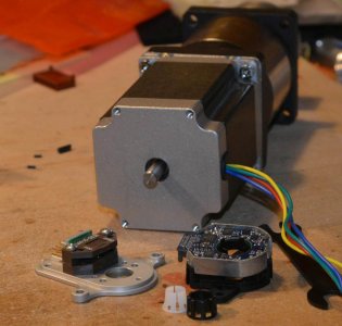
Spent some time thinking about how to mount the CUI or US Digital Encoder on the back of the stepper motor. Turns out the issue is mounting holes as there aren't any. Not like the SteppersOnline motor that I wish I had ordered.And just for general interest. The 3D parametric CAD drawing took less than 10 minutes. The CAM using AlibreCAM took about 25 minutes which includes generating and zipping the G-Code .ngc files.
I'm not suggesting anyone use the files but if you are interested in what I did.
How I would use them would be to:
1. 0.042" aluminum sheet a bit larger than the diameter placed onto scrap plywood or MDF and held in the corners. Ensure that the center point sits over a T-Slot.
2. Run the G-Code that cuts out the middle hole.
3. Hand drill through the plywood and with a large fender washer and a bolt anchor down the middle.
4. Next run the G-Code that does the center drilling for the mount holes and encoder holes.
5. Run the G-Code that does the 4 mounting holes.
6. Screw self tapping screws into the wood through the 5mm mount holes.
7. Run the G-Code to drill the encoder holes.
8. Finally run the G-Code to cut out the outer perimeter.
9. Remove the outer clamps, screws and bolt.
10. use a deburring tool to clean the perimeter if the edge is ragged. Same with the 14mm center hole.
11. Depending on the state of the encoder holes deburr from the rear with a hand tool.
12. Mount to adapter.
There. A 12 step program...
Not sure I want to take the back off the motor in order to drill and tap them. The shaft isn't long enough for a mounting plate that is thick enough to be threaded.
On the LinuxCNC forum counter sunk screws epoxied in was one suggestion. Or 3D print an expansion plate that matches up to the existing encoder mounting plate and then use JB-Weld to attach. Then mount to the outer mounting holes.
Or just remove the back plate and leave the armature in place to avoid screwing the magnetism.
Anyway, hopefully today I will cast the new mounts for the power draw bar and then tracking revolutions will become important. The option to put in my own disk is still there but first I think I want the works all mounted on the new castings before I decide if I want to go that way.
Attachments
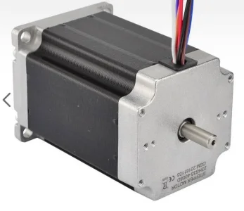

That was the original idea. But a plate that can take either threads or countersunk for a screw or threaded insert raised the plate enough that the encoder disk locking screw is just on the edge of the shaft. Not the longest shaft. Same issue with the CUI holder. If I'd restarted this project 3 days earlier I could have added a StepperOnline motor with all the AR3 Robot Arm motors and reduction drives etc. But a single motor at $33 with the holes already there along with $32 shipping all US $ turns into about $100 Cdn.I’m not sure how it all goes together but couldn’t you just make a new mounting plate for this?
View attachment 35924
I think I'll put a hold on this part until I cast the 3 draw bar plates and get them machined. It may well be that I can even run the stepper and planetary drive open loop with forwards for tightening at lower current than reverse for loosening. It will all depend on whether I can loosen what I've tightened. The desire for quadrature is so I can tell if it's stopped and not just vibrating against the stop.
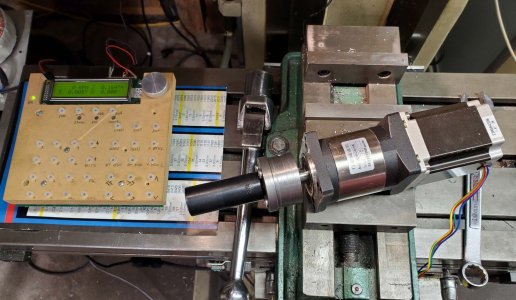
I thought I'd posted a photo of the new draw bar assembly but I don't see it in the older messages. The top ring keeps the vertical posts aligned.
Now it's the middle one that moves up and down with the air cylinder body.
The 25:1 planetary drive takes the 0.8 8 ft-lb static torque and makes about 22 ft-lbs. I figure I'll tighten at about 18 ft-lbs and loosen at full current.
What would be really cool is to have something sense the flat edge of a the draw bar nut and then turn the stepper motor until the socket lines up so it fits over perfectly. No collisions trying to go down with a locked draw bar in the spindle and and the socket on a locked stepper motor system.
I have a problem and I'm not sure how to solve it at the moment. The knee shaft has the usual square end. The pulley is not keyed but has the two set screws on the shoulder.

I can't just run the set screws down to press on the flats because if there is some sort of over torque event the screw part that sticks out bends. I've been using some brass pins pushed down by the set screws but ultimately it's the same issue. Some sort of sudden load and the pulley turns a bit, the brass pins are bent a tad and my Z axis has changed position slightly.

If I make a 25mm bushing with a 14.14mm square hole and then slice it into key like pieces I could then jam them down with the two set screws as long as the screws went into a dimple in the insert.

Alternatively put a flange on the insert with the square hole. As long as the set screws enter a dimple in the bushing it won't twist. I suppose it would be better if the bushing were keyed to the pulley.

Suggestions?
I can't just run the set screws down to press on the flats because if there is some sort of over torque event the screw part that sticks out bends. I've been using some brass pins pushed down by the set screws but ultimately it's the same issue. Some sort of sudden load and the pulley turns a bit, the brass pins are bent a tad and my Z axis has changed position slightly.
If I make a 25mm bushing with a 14.14mm square hole and then slice it into key like pieces I could then jam them down with the two set screws as long as the screws went into a dimple in the insert.
Alternatively put a flange on the insert with the square hole. As long as the set screws enter a dimple in the bushing it won't twist. I suppose it would be better if the bushing were keyed to the pulley.
Suggestions?
Does it have to have the square hole?I have a problem and I'm not sure how to solve it at the moment. The knee shaft has the usual square end. The pulley is not keyed but has the two set screws on the shoulder.
View attachment 36692
I can't just run the set screws down to press on the flats because if there is some sort of over torque event the screw part that sticks out bends. I've been using some brass pins pushed down by the set screws but ultimately it's the same issue. Some sort of sudden load and the pulley turns a bit, the brass pins are bent a tad and my Z axis has changed position slightly.
View attachment 36693
If I make a 25mm bushing with a 14.14mm square hole and then slice it into key like pieces I could then jam them down with the two set screws as long as the screws went into a dimple in the insert.
View attachment 36694
Alternatively put a flange on the insert with the square hole. As long as the set screws enter a dimple in the bushing it won't twist. I suppose it would be better if the bushing were keyed to the pulley.
View attachment 36695
Suggestions?
Seems to me that a round bushing with bore that clears the corner-to-corner dimension would support the majority of the grub screw stickout.
What about increasing the grub screws diameter and adding two more on the two other flats?
Aluminum.What's the pulley material?
Does it have to have the square hole?
Seems to me that a round bushing with bore that clears the corner-to-corner dimension would support the majority of the grub screw stickout.
What about increasing the grub screws diameter and adding two more on the two other fl
I think a square hole is a requirement. Although the entire pulley is pretty thick I could likely still broach a keyway in line with one of the set screws. Then make the square hole insert have a key way. If I can make the square be a press fit so it doesn't slop...