• Scam Alert. Members are reminded to NOT send money to buy anything. Don't buy things remote and have it shipped - go get it yourself, pay in person, and take your equipment with you. Scammers have burned people on this forum. Urgency, secrecy, excuses, selling for friend, newish members, FUD, are RED FLAGS. A video conference call is not adequate assurance. Face to face interactions are required. Please report suspicions to the forum admins. Stay Safe - anyone can get scammed.

G3616 Conversion.

At any rate, that isn't really what I was asking. My interest is much more mundane. What have all the wind turbines and solar farms done to daily max and min voltages and outage rates?
I stopped working for Ontario Hydro a long time ago in mid 90's so I'm not plugged in anymore, from what apI have read, delta V would be within the normal range and outage rates would be impacted more by reduced power system maintenance than the additional generation. The latest inverter based generators will help with many aspects; system stability, voltage dips, efficiency and outages, they can actually operate as an island and help restore the grid when it is taken down, so in short more good than bad.


Your friends comments about NUG make complete sense. The Wikipidia explanation appears to be accurate. I can say that I lived in Manitoba for about 20 years and their power system is lower cost and more reliable, however they are blessed with lots of hydro. IMO Ontario would be better off purchasing power from our two Canadian neighbours than their latest plan.
 
Last edited:
Here's the reply from Donald Chen at Bergerda.
Let us back to business, our quotation for

750W 80SM-M0230NAL and SDD08NK8D with 3 meters cable are 290USD
800W 110SM-M0420NAL and SDD13NK5D with 3 meters cable are 320USD

Now the shipping cost is cheaper than before, let me know his decision to check the shipping cost
Thank you John

Best Regards

Donald
I've asked him for a link to the latest manuals.
 
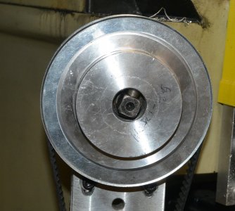
I've not been able to mill out something that has a friction fit over the square part of the knee shaft. Likely because it's not really cut to a fine tolerance not to mention slightly raised marks from set screws.
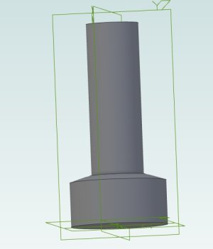
So instead of using under size brass screws as pins I thought I'd turn a steel one on the lathe. The bevel is so it follows the 1" ID of the round part of the pulley bore.
PulleyPin-Drawing.jpg

It seems to be working better than the brass one. I've only made one and used the two screws, one to press it down on the shaft and one to lock the first. I think it's twisted the pulley slightly so one on the other side would probably be better but that means trying to create a completely symmetrical hole.
PulleyPin-Photo.jpg
I have some other ideas too. Perhaps just a spacer on the other side.
 
So a while back I was changing the power draw bar over to a stepper motor and planetary reduction drive. I decided to add an encoder to the motor so I can detect how many turns and when it's unable to tighten any further. The goal is to be able to set the current into the motor for tightening at a lower value than for loosening. So I should always be able to loosen the draw bar.

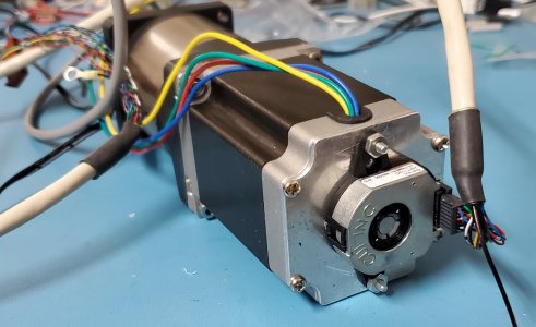
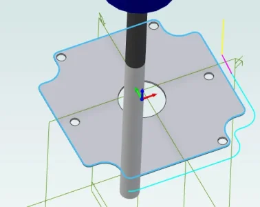
Trouble is the stepper motor I had does not have mounting screws on the back for an encoder and I didn't want to take the chance on pulling it apart and destroying it or drilling/tapping into the back and damaging it. The back shaft is very short. No room for a thick mounting plate so I made a thin one. Here's the result.

20230729_180017.jpg
The four little 3mm screws just fit nicely into the left over thread on the back side of the motor cover. The two encoder mounting screw holes were counter sunk from the back side and two 4-40 flat head screws with most of the bevel turned off were epoxied into place serving as mounting studs.

So how did I make it?
Obviously CAD/CAM first. AlibreCAD and then AlibreCAM (MecSoft CAM).
ProfilingMountingPlate.webp
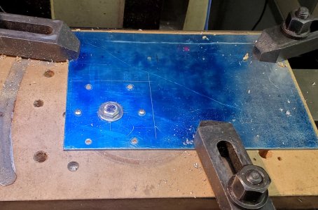
Once the holes were drilled I ran a 1/4" bolt down the middle into a T-Nut and a couple of self tapping 3mm screws to keep it from turning.
20230729_131410.jpg
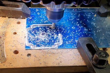
Then mill the outside profile and clean up the holes and about 0.019" per pass for depth of cut. Speed 18 IPM at about 2600 RPM with a 1/4" two flute end mill.

20230729_131510.jpg
Now to whip up some sort of connection to the encoder and write the software to track that it's moving and how far it's moved.
 
Long ramble here.

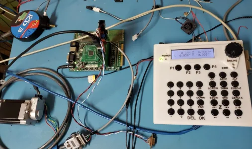
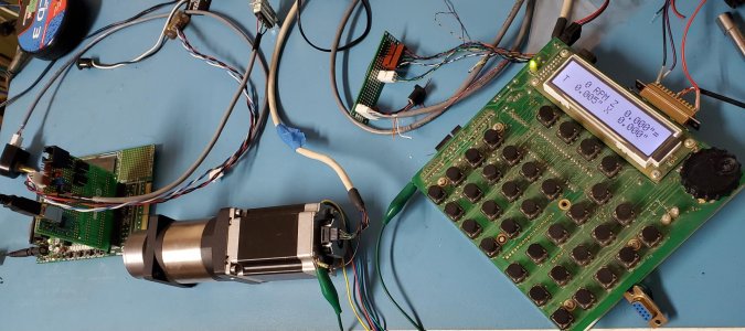
I can't yet test the motor mounted to the planetary drive because the CUI encoder uses a connector that I don't have. Or if I did I don't know where it went. So I used the second mounting plate to put one of my US Digital Encoders (250 lines per rev) onto the back of the other stepper motor. Made up a cable to replace the panel mount encoder into the dsPIC33 test set.

I did actually start writing the software for the dsPIC33 to also send out step/dir pulses and then decided to do it that that was way too much work. Instead grabbed the ELS from my Gingery Lathe and wired it up to my external power supply and Bergerda stepper driver.
EncoderTest.webp
What a hodgepodge of wires.

I reprogrammed the ELS with the debug messages enabled so I could see what it was sending out. Then configured it for 50 passes 1" long and told it to run. After 53 passes (50 plus 3 spring passes) the mark on the stepper motor, after move back to 0.000 lined up perfectly as did the encoder position which started at -1. (the second position line is motor degrees).
After all that I then sent it to do a single pass and stopped it at the end.
Main (S3) Show Encoder
Velocity: 0
Position: -10001
Position: -2250.2

So what does it mean?

It's a 10 TPI lead screw in the configuration. That means 1 turn of the lead screw for each 0.1" and that means one turn of the motor shaft is 0.1" Since it's 250 lines on the encoder the quadrature mode means 1000 pulses per rev and to move 10 revolutions is therefore 10,000 pulses. The motor driver is set up for 1600 steps per rev as is the ELS.

Oh and here's a bit of the diagnostics. The ELS is running in Broach mode so the spindle doesn't need to turn. It's just doing 50 passes of 0.001" per pass with a thread depth of 0.050. The tool bit is programmed to follow the standard 29.5 degrees along the thread flank. It does this by shifting over a bit on each pass as it goes deeper on each pass.

Here's the diagnostics for the last pass.
Move: TO_END
Move: AT_END
Move: WAIT_END_OUT
Move: WAIT_END
X= 0.0500, Z= 0.0283
ZS=453, ZE=16000, XS=-2400, XR4800
Return To Start ... Move: WAIT_TO_START


The X depth at the end was 0.050 which is correct. The Z End position is 16000 which is 10 turns of 1600 steps per turn.
The Z starting position was originally 0 but has moved to the left by 453 steps or 0.0283". And if we do arctan(z/x) we get arctan(0.0283/0.050) = 29.5 degrees. So that matches the ELS parameter for thread angle.

I had to press the ALT-Z_HOME button on the ELS to move it back to the original BEGIN position. And the encoder counter reported -1. Exactly where it started.

This encoder caused a lot of issues on the DC servo motors which is why I switched to CUI encoders. But even with single ended outputs mechanically on the end of the stepper motor it appears to be working quite well.
 
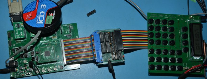
BTW, just to add some info. Why if I've made a prototype of a 32 bit PIC32 interface to the original ELS did I use a 16 bit dsPIC33 for testing the encoder software?
AdaptorBoard-7.jpg
Well the Automotive Networking Board on the left side of the photo has a PIC32MX795 PIM module. That PIC processor has Ethernet and USB capabilities but does not have quadrature encoder hardware. So it was easy enough to port the 8 bit ELS software over to it and discover it was running more than 10x as fast but I didn't want to do a software quadrature encoder. I'm already doing that for the MPG knob on the ELS.

And it does work:
Project ELS_PIC32 ANB Revision 0.10b
E_ : EEROM Operations
f : Show Control Flags
t : track Spindle SpinRate value
s : show system states and flags
m : Dump menu list
v : ELS PIC32 Version
?Hh : This Help Menu>


So way back when I was working on this project I ordered four PIC32MK1024MCM064 processors with 1MB flash memory. The processors are only $14 and are expected to be in stock again in September. Luckily I have 4. A while ago it was more than a year to get more which is why I put the project on hold.

So I think I'm at the point where I can now finally get around to laying out the PC Board for the PIC18 CPU replacement.

If anyone is interested here's the latest schematic for the adapter. It will likely be a 4 layer PC board with some extra I/O. And since I had a few extra pins I've brought a Y axis out to the DB-25. And there are jumpers to reroute a couple of pins so that the Chinese Break Out Board can connect directly.

If I've done it right then this can become the Draw Bar and tool changing Controller. Buttons to release and load TTS or R8 Tools (2 revolutions or 18). Communications with LinuxCNC is via CAN bus. Depending on what I end up using for a tool carousel if there isn't enough I/O the CAN bus can expand extra I/O. But I can have a load tool button and select which tool number.

Finally because I've added the Y axis this version could also become an ELS for a mill. With simple power feed from a BEGIN to END position. Etc. Depends how fast I finish the other 42 projects in front of that.
 

Attachments

I found the cable!

CUI encoder now mounted. Yikes. Way more sensitive to electrical noise.
Mounted_CUI_Encoder.jpg

Since the encoder has differential outputs it's clear that I should add a set of receivers as close as possible to micro-controller. The CUI manual does say to connect the shield wire directly to the motor. It was still a bit flaky. A clip lead from that point to the heatsink (ground) of the ELS and it suddenly became very solid.

Why the difference between the CUI and the US Digital with the same type of motor?

Well the CUI is a capacitive encoder that has a processor that creates the resolution programmed in via a serial port and PC application and creates the quadrature outputs. It's possible without good grounding and shielding that it's more sensitive.

The US Digital (with this version having its own bad rep) is optical with 250 lines on the disk so the two optical sensors create the quadrature outputs. So there's no indeterminate values based on noise or load. More absolute.

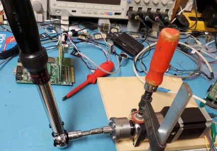
Think I might connect a socket and torque wrench to it and see when step pulses stop increasing the encoder. I can just keep increasing the torque wrench settings and stepping until it no longer goes click. See if the motor will really create 20 ft-lb.
 
Alright. Just had to try this.
TorqueMeasurementSetup.webp
Static torque with no motor motion and at 240 in-lbs (20 ft-lbs)the torque wrench easily clicks and the motor doesn't move.
Then jog slowly applying torque to the wrench and it also clicks.

When I apply 240 in-lbs to the actual draw bar with this torque wrench it's tighter than I normally do by hand with a wrench.

I think a fast move turning the drawbar until the motor locks up as indicated by the encoder. Stop and restart then turning slowly until it locks up again and it will be at whatever torque the current through the motor windings are set to.

To release, just increase the current to the full 3A, and turn counter clockwise for two turns for TTS holders. If the draw bar is captured correctly it will push the R8 collet down and the TTS holder will just fall out.

Baby steps.
 
Here's the reply from Donald Chen at Bergerda.

I've asked him for a link to the latest manuals.
John,

Very interesting thread. I read it some months ago before I purchased my knee mill and was intrigued by the transition from stepper to dc servo to ac servo.

Fast forward and I realize that some of my decision making for my still underway CNC knee mill conversion were influenced by this thread.

For my project I'm using ballscrews, ac servos and scales. Plan is to use LinuxCNC and I have a MESA board. I have a few questions that will help me with the next few steps:

1) Did you measure the torque required to lift the knee?

2) LinuxCNC is all new to me, all I have done so far is load it on a PC and execute the latency test. If I understand things correctly during the install you can select from a multitude of variations of the GUI and then can or possibly be required to tweak your chosen flavour to your specific mill. What variation are you using? And now that your using it and understand its benefits and possibly limitations would you use a different variation knowing what you know now?

I converted my old RC mill to CNC using steppers and Mach3, with Mach I find I only use a few pages; the gcode execution page, the MDI page (for general moving around and simply say 3-4 line sequences by using the up key to recall one of the 3-4 sequences entered), and the page with the scale driven DROs. I'm not sure what LinuxCNC variation would best offer those features?

One thing I think is possible with LinuxCNC (not sure) is the ability to close the servo loop with the scale data?

The picture in my head is: let's say we're at 0,0,0 and I execute G0 1.000 and for whatever reason (backlash, ballscrew error, whatever) the servo moves 1.000" but the actual table (according to the scales) is actually now at 0.9990. I think LinuxCNC can use the scale data to correct the 0.001" error and add required additional steps to the servo to get to actual 1.000" according to the scales. Do you know if this is possible?

3) Last question is how did you go about tuning your ac servo PID loop and was it difficult?

Much appreciated,

Jeff
 
Last edited:
John,

Very interesting thread. I read it some months ago before I purchased my knee mill and was intrigued by the transition from stepper to dc servo to ac servo.

Fast forward and I realize that some of my decision making for my still underway CNC knee mill conversion were influenced by this thread.

For my project I'm using ballscrews, ac servos and scales. Plan is to use LinuxCNC and I have a MESA board. I have a few questions that will help me with the next few steps:

1) Did you measure the torque required to lift the knee?
Yes. I used a flex handle with socket and hung weight on it at 12" to determine ft-lb. Then started with a 500 oz-in stepper with a surplus pair of 3:1 pulley and belt setup. It worked but was way too slow for anything but a crawl upwards. I doubled the size of the motor still using a Gecko stepper motor driver and achieved 25 ipm which was usable even if it still felt slow.
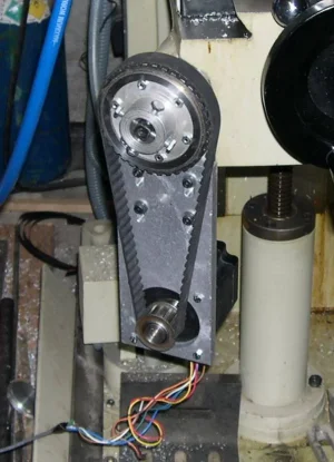
1703696890434.webp

At the back of the cross drive to the knee screw was a thrust bearing and (maybe?) bushing.
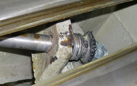
1703696998391.webp

I replaced that with a bearing.
1703697074203.webp
I have more pictures of all the parts if you want.

Anyway. When the Gecko drive died I had a choice to just replace that or go for servo. I looked at the 25 ipm speed and the stepper motor torque curve and the torque at that speed and decided I'd replace it with an AC Servo that had that torque over the full RPM range. I can now run 150 ipm which is scary fast for the knee.

2) LinuxCNC is all new to me, all I have done so far is load it on a PC and execute the latency test. If I understand things correctly during the install you can select from a multitude of variations of the GUI and then can or possibly be required to tweak your chosen flavour to your specific mill. What variation are you using? And now that your using it and understand its benefits and possibly limitations would you use a different variation knowing what you know now?
I use AXIS. I've played around with other user interfaces on the Pi4 with a smaller touch screen and those user interfaces but I haven't changed the main system. I have a USB wired MPG that I use a lot so the touch screen idea hasn't made it into the shop. In many ways the mill is a hobby project in process so I may not be as fussy as some. I have been considering changing to the Tormach user interface but haven't tried to install that yet. Not even sure what's involved but it's closer to MACH than any of the others.
I converted my old RC mill to CNC using steppers and Mach3, with Mach I find I only use a few pages; the gcode execution page, the MDI page (for general moving around and simply say 3-4 line sequences by using the up key to recall one of the 3-4 sequences entered), and the page with the scale driven DROs. I'm not sure what LinuxCNC variation would best offer those features?
I use 3 screens now in AXIS. The Main screen where I can jog and run etc. The MDI screen which I type in commands. The scroll back buffer is really large and visible so it's easy to type something and then select something 20 lines back with the mouse. I now also have the touch screen for my probe. For that I need to write up (for myself) better directions as I have trouble remembering things.

For example: Probing the inside of a hole to find the center. It was easy to do, although a bit tedious with the wired probe and Shumatech DRO. Now there's a distance to enter for high speed motion so you set that to a bit under the radius of the hole. Position the probe close to the middle and it moves quickly to the edge and then slowly till it touches. It then backs off and goes really slowly to find the position. Then fast back to the opposite etc. for 4 times to find and set the origin to the center of the hole. Remember which parameters to set is where I have issues. But it works well and automatic.
One thing I think is possible with LinuxCNC (not sure) is the ability to close the servo loop with the scale data?
Yes. If you get the correct MESA boards with enough inputs LinuxCNC can do that and apparently it does it really well. My scales are so cheap that I decided it wasn't worth it. And yet, it was the Shumatech DRO that pointed out one of the DC Servo motors I originally installed was losing position. After a few cuts didn't line up correctly.

Short and long of that story is I changed to the Bergerda AC Servo's and have never looked back.
The picture in my head is: let's say we're at 0,0,0 and I execute G0 1.000 and for whatever reason (backlash, ballscrew error, whatever) the servo moves 1.000" but the actual table (according to the scales) is actually now at 0.9990. I think LinuxCNC can use the scale data to correct the 0.001" error and add required additional steps to the servo to get to actual 1.000" according to the scales. Do you know if this is possible?

3) Last question is how did you go about tuning your ac servo PID loop and was it difficult?
The Bergerda's pretty well worked perfectly right out of the box. I did have trouble with one axis. I contacted Bergerda with the settings I had and one of their engineers figured out what I needed to change. Don't remember exactly what happened but apparently one of the default parameters on the drive was incorrect. I found the controllers easy to work with.

About the only mistake I think I've really made is being in love with 150 ipm for Y and 180 ipm for X. It's cost me one probe so far because I had an incorrect parameter while mucking around with custom probe software.

Much appreciated,

Jeff
I have found the Enhanced Machine Controller (EMC) <[email protected]> email list invaluable and the people on that list have been very helpful.
For example I asked about other user screens and Andy Pugh posted the reply.

> Suggestions are welcome. If Touchy is simpler than AXIS perhaps that's a starting point?
Touchy is Python and a Glade UI, axis is Python and a UI defined by Tcl.
Touchy is probably simpler.
You could just start with Gscreen. It a UI framework, intended for customisation, but already all working.

Andy Pugh just posted this to the list:

LinuxCNC 2.9.2 has been released. This is a bugfix release, with the most obvious change being that run-from-line in the Axis interface should now be working again.
Packages have been prepared for:
Buster - uspace - amd64 (PC) armhf (Pi) arm64 (Pi with 64-bit kernels) Buster - RTAI - amd64 Bullseye - uspace - ams64 (only) Bookworm - uspace - amd64, arm64 Bookworm - RTAI - amd64
For existing users of 2.9.1 on the above platforms this should be offered as an automatic update.
If anyone badly needs Bullseye debs for RTAI or arm64 / armhf then let me know. (all but the amd64 uspace builds have to be manually created)
Contributors to this release are:
Alec Ari
andypugh
c-morley
dps.lwk
Greg Carl
Hans Unzner
H vard F. Aasen
Moses McKnight
Norbert Schechner
Peter Wallace
Petter Reinholdtsen
Phillip Carter
Rene Hopf
Sebastian Kuzminsky
Sigma1912
Steffen Moeller

Peter Wallace is the MESA board designer and supplier. Sebastian Kuzminsky does BeagleBone stuff etc. Rene Hopf designed the STMBL servo drive I use for the 4th axis and bought to repalce the UHU drivers for my DC servos before I discovered the motor issue on X axis.
Everyone has been very helpfull. Some of the online LinuxCNC forums have the usual evil trolls trying to up their support message count by replying and then if the reply is questioned they reply again with "You aren't listening". So I tend not to visit those forums.

Hope that helps.
 
Yes. I used a flex handle with socket and hung weight on it at 12" to determine ft-lb.

John,
Yes very helpful.

Did you record the torque required to start and move your knee? I'm curious how that measurement compared to the torque specifications of the three motors?

I will measure here, I did that for X and Y. Your knee is larger than mine, so I would expect the value will be lower on my smaller mill. I'm mulling over different approaches to mounting the knee servo, they all have advantages and disadvantage:

1) direct connection to the hand crank stub
2) reduction with pulleys (as you did)
3) some sort of internal in the knee mount.

IF my knee is a fair bit lighter than yours, and IF the resulting torque required is also a fair bit less it might be possible to use option 1 above. Which is simple and I like simple. On the other hand I do like the way the servo gets tucked out of the way with method 2.

Decisions, decisions.....

I will join the EMC mailing list, thanks for the tip.

Peter Wallace- MESA, we corresponded when I was deciding on which MESA card.

Thanks,

Jeff
 
Last edited:
Working backwards looking at the torque curves I'm going to guess I needed about 637 oz-in (4.5NM) to turn (3:1) the 4 TPI knee shaft to achieve 25 IPM. After that it would randomly lock up.

The 80SM-M0320MAL AC Servo is rated continuous 3NM peak 10.5NM and 2000RPM. I couldn't get the Stepper up above about 325 RPM into the 3:1 reduction. So I went from 25 IPM to roughly 6x that; 150 IPM. Since the peak torque can be 10.5NM any momentary loads appear to be covered.
What's interesting is the drive shows things like RPM or Current on the LED display. Rated Current is 3A and peak is 9A. I don't ever see the display get even close to 3A so I suspect my 730W motor is a tad oversized although physically it's not that big.

Key thing is steppers are good at low speeds where their torque value is highest. Their down side is falling off at higher speeds. Servos have a lower constant torque setting but they have it over the full RPM range along with that nice Peak value. But to make use of that on equipment you often have to add a reduction drive in order to not exceed max speed in other areas. And you get torque multiplication so the motor ends up being quite small.

The other plus side of pulleys is positioning of the motor. Doesn't have to stick out and alignment isn't an issue. And yes, compared to stepper motors servos are more expensive. Especially when you add in pulleys etc.

This is one of those things where after you've had servos you never want to go back.
 

Attachments

Not that uncommon a problem when I was doing calcs. Steel is 0.27 lbs per cubic inch. My guess is the knee would be about 30% of the weight of an equivalent solid block with the same w/l/h. 5 tpi will be about 15% higher thrust than 1-4 tpi. My designs tended to be way more robust than ones calculated by real engineers, but in 45 years I never had one fail.
 
Two issues. No idea how to determine the weight of the knee short of removing it with the entire XY and pivot X assembly. Second, no 1"x 4 TPI in the list.

Can't you just measure it with a torque wrench? Even a fish scale would be good enough cuz you are gunna add a fudge factor anyway.
 
Can't you just measure it with a torque wrench? Even a fish scale would be good enough cuz you are gunna add a fudge factor anyway.
That's exactly what I did. And I also did the weights on the arm. That's why I figured the 600oz-in motor would work with 3:1. Problem is to get speed the torque fell off too fast. I'd have had to have an 1800 oz-in motor for direct (or 1:1 pulley).

That torque curve for stepper motors is critical. And even then they aren't totally accurate because they usually state half step speeds and higher microstepping is required for handling resonance.
 
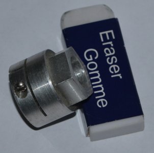
This is how I measured the torque needed on the South Bend Lead screw. I was surprised how low the requirements were but I also don't do massively heavy cuts on this 1942 vintage beast.

TorqueTestAdaptor.jpg
Clamp onto the lead-screw shaft. Then add a socket and flex handle and dangle weights. I tried a fish scale but it was too strong and didn't even register. It was back to how fast do I want it to run given that my ELS internal micro-stepper drive had a 3A max drive at 55V. (LMD18245's).
 
I have a very sensitive torque wrench, it worked well for the X and Y axis measurements, when I have a chance I will post results for the knee.
 
If I understand what @jcdammeyer is looking for, it is the dynamic torque at startup, not the static torque it takes to turn it. The dynamic torque required to spin the gear train up could be quite a bit higher than the static torque required to just get it turning.

Such a measurement might require a torque transducer and a plot of the torque value as it changes with acceleration.

Another way to do it might use a torque limiter and just keep reducing the torque till it works as desired.
 
Back
Top