Next in line is the arm to hold the keyboard and monitor and be able to fold back out of the way above the cart. The downloaded step file had some issues with bevel angle. I started from scratch and created a new Hirth joint with 60 degree angles. Fits perfect.
-
Scam Alert. Members are reminded to NOT send money to buy anything. Don't buy things remote and have it shipped - go get it yourself, pay in person, and take your equipment with you. Scammers have burned people on this forum. Urgency, secrecy, excuses, selling for friend, newish members, FUD, are RED FLAGS. A video conference call is not adequate assurance. Face to face interactions are required. Please report suspicions to the forum admins. Stay Safe - anyone can get scammed.
-
Several Regions have held meetups already, but others are being planned or are evaluating the interest. The Calgary Area Meetup is set for Saturday July 12th at 10am. The signup thread is here! Arbutus has also explored interest in a Fraser Valley meetup but it seems members either missed his thread or had other plans. Let him know if you are interested in a meetup later in the year by posting here! Slowpoke is trying to pull together an Ottawa area meetup later this summer. No date has been selected yet, so let him know if you are interested here! We are not aware of any other meetups being planned this year. If you are interested in doing something in your area, let everyone know and make it happen! Meetups are a great way to make new machining friends and get hands on help in your area. Don’t be shy, sign up and come, or plan your own meetup!
You are using an out of date browser. It may not display this or other websites correctly.
You should upgrade or use an alternative browser.
You should upgrade or use an alternative browser.
G3616 Conversion.
- Thread starter jcdammeyer
- Start date
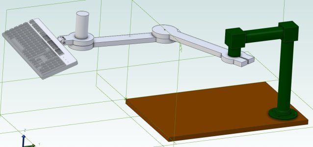
The drawing was mostly just to figure out the lengths The plan is to make it massive to avoid the bouncing.Looks like it will bounce around too much while typing
There are some other ideas like a drop down foot. or a brace back to the cart.
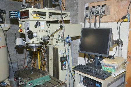
When I push the cart back in beside the mill and home the X it will become obvious why the cart has to be so far back. It would be worse if i had the G3617 equivalent with the 25% longer table and horizontal spindle. Still wish I'd bought that one from House of Tools. But I didn't have the space then and still don't.
You would get more rigidity (less bending deflection) if your arms used rectangular section stock with the long axis vertically vs horizontally like your sketch. Its essentially a cantilever beam.
The arms themselves also have their own weight to consider so depending on the load & span lengths, something like aluminum tubing might work. Comes in different wall thickness.
Those adjustable detente clamps might give you quick adjust ability & position lock on the axles, they have common threads
Yes. It was initially easiest to draw simple flat sections to work out how long to make things so that when folded away it would still work. I will likely make something that is lightweight but has very little flex. The pivot could easily be 4" tall.You would get more rigidity (less bending deflection) if your arms used rectangular section stock with the long axis vertically vs horizontally like your sketch. Its essentially a cantilever beam.
But you are 100% correct that it needs to be strong since it will hold the monitor too.
Attachments
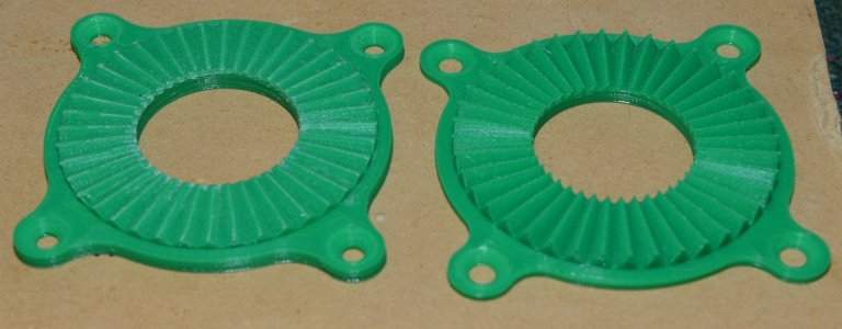
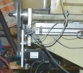
Been a while since I've posted anything. Been very busy with work stuff. Finally an opportunity to get the encoder part of the CNC conversion working. To put it into perspective here's a photo of the turned pulley with the machined (via CNC) encoder disk with 60 slots.

Notice the bolts holding the housing onto the main head assembly. It sits around the actual bearing holders and it turns out isn't symmetrical from the perspective of where the bolts are and where the center line of the pulley/disk/spindle is.
I wanted to mount the slotted sensors onto a plate that was raised up. A suggestion was made that I center drill the bolts with 10-24 and then mount the plate on spacers on top of the head of two of the bolts. Well I broke a tap on drilling and tapping one of the bolts. Someone suggested just make my own bolts.
My ELS on my 1942 imperial lathe can cut metric I made two bolts that included the spacers.

Now the heads of the bolts were at the right height and had the 10-24 threads so I 3D printed the sensor holder.

There's extra bracing on the 3D print to keep everything stiff. Then just mount the sensors.

The were a bit too low. The teeth of the encoder brushed against the edge of the sensors and the slots were in the wrong place on the brackets because the aforementioned mount holes were not symmetrical with the spindle center.

After a visit back to the 3D printer and a small adapter board I had A,B and Z into the MESA 7i92H. Some tweaking of position monitoring the pulse train with the scope which reports correct RPM because 60 pulses per rev turns into RPM on the scope frequency measurement.
More in the next posting.
Notice the bolts holding the housing onto the main head assembly. It sits around the actual bearing holders and it turns out isn't symmetrical from the perspective of where the bolts are and where the center line of the pulley/disk/spindle is.
I wanted to mount the slotted sensors onto a plate that was raised up. A suggestion was made that I center drill the bolts with 10-24 and then mount the plate on spacers on top of the head of two of the bolts. Well I broke a tap on drilling and tapping one of the bolts. Someone suggested just make my own bolts.
My ELS on my 1942 imperial lathe can cut metric I made two bolts that included the spacers.
Now the heads of the bolts were at the right height and had the 10-24 threads so I 3D printed the sensor holder.
There's extra bracing on the 3D print to keep everything stiff. Then just mount the sensors.
The were a bit too low. The teeth of the encoder brushed against the edge of the sensors and the slots were in the wrong place on the brackets because the aforementioned mount holes were not symmetrical with the spindle center.
After a visit back to the 3D printer and a small adapter board I had A,B and Z into the MESA 7i92H. Some tweaking of position monitoring the pulse train with the scope which reports correct RPM because 60 pulses per rev turns into RPM on the scope frequency measurement.
More in the next posting.
OK. So once I had valid quadrature outputs I tweaked the HAL and INI settings and finally had spindle RPM from the sensor and switched over from PWM 0V-10V to step/dir to the spindle. The two pulleys weren't exactly 1:1 so I changed the ration of pulses per rev for the spindle and now asking 1000 RPM gives 1000 RPM on the spindle. No PID stuff needed.

Following the directions from one of the LCNC links I created a tool table.

Then wrote some G-Code to load tool #1 and center drill the piece of round stock in the photo. Just a small dimple to guide the drill bit.
Back to the tool change position and remove the center drill and install the chuck with #21 drill bit.
I used a peck drilling G-Code with 1000RPM.
Back to the tool change position. It stops and waits for an OK button click on the screen. Install the 10-32 tap and click OK.
Now the scary part. Watch it rapidly move to 0.1" above the work and then shoot over at 150ipm to the vise holding the piece.
Just clears it of course since the new tool changes the zero position. And then the spindle starts turning at 200 RPM and the knee moves up at a rate that matches the 200 RPM. The tap enters and cuts threads. At 0.7" depth it stops, the spindle reverses and the tap exists. Too cool really.
A cleanup with a deburring tool on the hole entry and the brass 10-32 screw threads in perfectly.
The next day the fully spiral (rather than spiral tip) tap arrived from amazon.ca. I added a #7 drill bit and the 1/4-20 tap. After some issues with setting the tool heights etc I ran the same program with the G-Code set for 0.050 pitch threads. Wow! Spiral chips from the tap coming out the top. A 1/4-20 bolt threaded in smoothly.
I need to clean up the wiring of course so the spindle sensor is more permanent and eventually I'll change to all metal mounts but this was a fun project. Learned all about offsets etc. in CNC. A few collisions and drilling in the wrong place were part of the learning process.
Next project is mist cooling which requires air. And once the air fittings are there I'll install the Princess Auto butterfly impact wrench as a power draw bar. That will make tool changes easier.
Following the directions from one of the LCNC links I created a tool table.
Then wrote some G-Code to load tool #1 and center drill the piece of round stock in the photo. Just a small dimple to guide the drill bit.
Back to the tool change position and remove the center drill and install the chuck with #21 drill bit.
I used a peck drilling G-Code with 1000RPM.
Back to the tool change position. It stops and waits for an OK button click on the screen. Install the 10-32 tap and click OK.
Now the scary part. Watch it rapidly move to 0.1" above the work and then shoot over at 150ipm to the vise holding the piece.
Just clears it of course since the new tool changes the zero position. And then the spindle starts turning at 200 RPM and the knee moves up at a rate that matches the 200 RPM. The tap enters and cuts threads. At 0.7" depth it stops, the spindle reverses and the tap exists. Too cool really.
A cleanup with a deburring tool on the hole entry and the brass 10-32 screw threads in perfectly.
The next day the fully spiral (rather than spiral tip) tap arrived from amazon.ca. I added a #7 drill bit and the 1/4-20 tap. After some issues with setting the tool heights etc I ran the same program with the G-Code set for 0.050 pitch threads. Wow! Spiral chips from the tap coming out the top. A 1/4-20 bolt threaded in smoothly.
I need to clean up the wiring of course so the spindle sensor is more permanent and eventually I'll change to all metal mounts but this was a fun project. Learned all about offsets etc. in CNC. A few collisions and drilling in the wrong place were part of the learning process.
Next project is mist cooling which requires air. And once the air fittings are there I'll install the Princess Auto butterfly impact wrench as a power draw bar. That will make tool changes easier.
What spindle taper does that machine have?
Sent from my iPhone using Tapatalk
Sent from my iPhone using Tapatalk
It has R8.What spindle taper does that machine have?
Sent from my iPhone using Tapatalk
Under the head of the draw bar I have a WUT. Rick Sparber's WUT
The tooling you see is older vintage and Chinese TT Tool holders. The mill has a flattened 3/4" R8 holder so for most of the tools in the tool table I can set the height of each tool once and don't have to touch off each time.
But I have some R8 tooling, like a big drill chuck and a floating tap holder, that require removal of the special R8 TT Holder Collet.
I have the plans and parts for this and looking at building it. Power Draw bar from Butterfly Impact Wrench
This is the quandary I'm in at the moment. Using a Butterfly impact wrench for a power draw bar results in nice and fast tightening but making the impact wrench only turn one revolution or so for unloading is looking to be really difficult. If it spins too far then the entire R8 collet also comes out and that defeats part of the purpose of the TT holders. They only need to back off about a turn or two and then the tool drops out.
But you know how it is with an impact wrench. Chugga Chugga Chugga and then Scream at 100 RPM or more. I want the Chugga's but not the Scream. If scream is the right description for a fast turning air impact wrench.
Although I bought all the air bits for this about 12 years ago I'm now thinking that a 100:1 planetary gear box and stepper motor might be a better solution. A dual shaft size 23 motor could have an encoder on the back and the control can then tighten the stepper until it skips. Setting motor current then sets max torque after the 100:1. Like a 5.25" disk drive homing on startup. Send it a few extra steps past what it can move and it is guaranteed to reach the end stop at which time you can set zero.
To unlock the TT Holders I can unwind it two turns. If I call for an R8 holder I can unwind it 10 turns. But with shipping and all the planetary drive will be $100. Still need the motor etc and all the other work to control it.
Quick update. Yet again while center drilling and then prepping for hole drilling I found the X axis has once again started losing position. A return to G54 X0 results in the Dro showing as much as -0.024" And it just accumulates when I run a test program each time.
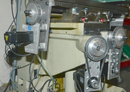
OK. So the original two motors ordered at the same time from AutomationTechnologiesInc were supposed to be identical. However after initial testing a few years ago (they were bought more than 10 years ago) showed one had twice the winding resistance of the other. The clue was one got quite warm and the other didn't. The one that got warm matched the winding resistance of the spec sheet so I put that one on the higher loaded Y axis.
The X axis got the other one and that's the one showing errors. No problem. In less than an hour I'd unbolted, changed pulleys, and mounted the swapped motors. Ran the test G-code program and sure enough the slowly increasing errors now shows up on the Y axis and the X is perfect.
One mistake I'd made last year was thinking the DC Servos were 1.27NM when in fact they were 1.6NM. I was worried that if I put one of the Bergerda AC servos on the Y axis it might not be big enough. So I made up the mount, pulled out the 15mm ID pulley I'd bought a year before (the DC servos had 1/2" ID) and connected it up.
Ran the test program and no position errors on Y. The Bergerda drive can report current or torque. It's a 2.8A motor that never uses more than 1A and most of the time it's in the 0.4 to 0.6 range. Max torque was 0.43 which is 34% of motor max torque. BTW, after the 4:1 pulley and max 750 RPM on the lead screw that matches what a 1200 oz-in stepper motor would do at about 750 RPM.
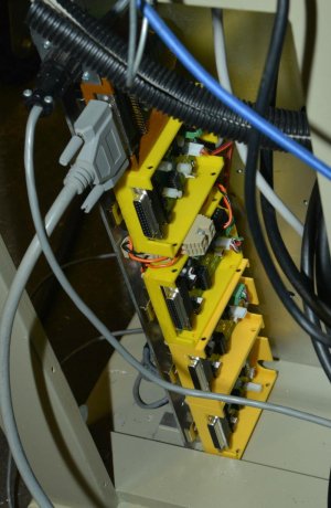
Anyway, I've pulled the HP_UHU drives from the cabinet. Installed two more interface modules for enable/step/dir/fault with differential signals to the Bergerda. Need to do a bit more wiring and then I'll have a full AC servo driven machine. Don't even need the panel with the 16V power supply anymore.
More when it's working properly again.
OK. So the original two motors ordered at the same time from AutomationTechnologiesInc were supposed to be identical. However after initial testing a few years ago (they were bought more than 10 years ago) showed one had twice the winding resistance of the other. The clue was one got quite warm and the other didn't. The one that got warm matched the winding resistance of the spec sheet so I put that one on the higher loaded Y axis.
The X axis got the other one and that's the one showing errors. No problem. In less than an hour I'd unbolted, changed pulleys, and mounted the swapped motors. Ran the test G-code program and sure enough the slowly increasing errors now shows up on the Y axis and the X is perfect.
One mistake I'd made last year was thinking the DC Servos were 1.27NM when in fact they were 1.6NM. I was worried that if I put one of the Bergerda AC servos on the Y axis it might not be big enough. So I made up the mount, pulled out the 15mm ID pulley I'd bought a year before (the DC servos had 1/2" ID) and connected it up.
Ran the test program and no position errors on Y. The Bergerda drive can report current or torque. It's a 2.8A motor that never uses more than 1A and most of the time it's in the 0.4 to 0.6 range. Max torque was 0.43 which is 34% of motor max torque. BTW, after the 4:1 pulley and max 750 RPM on the lead screw that matches what a 1200 oz-in stepper motor would do at about 750 RPM.
Anyway, I've pulled the HP_UHU drives from the cabinet. Installed two more interface modules for enable/step/dir/fault with differential signals to the Bergerda. Need to do a bit more wiring and then I'll have a full AC servo driven machine. Don't even need the panel with the 16V power supply anymore.
More when it's working properly again.
Attachments
Sorry I missed your request earlier. It's a Bergerda.What is the make/model of the servo? I'd like to find the spec sheet and connections for it.
http://en.bergerda.com/
You do mean the AC servo?
The DC servo is from Automation Technologies Inc. and the drive is an HP_UHU kit. Encoder was US Digital but gave problems so switched to CUI.
Given the problems with the X axis I'm now wondering if the US Digital wasn't a fault but the motor. The Y axis matches the spec.
Both DC servos have been replaced. Wiring completed to the interface modules that take the 5V single ended step/dir signals and turn them into differential, bring back the fault and supply the ENABLE signal from the DB25-1. Any single fault from one of the 5 motors will stop all of them.
The Bergerda Servo drive can report current consumption. At most running the X axis with 3:1 and 3000 RPM the total current draw is never about about 0.6A. It can also report the encoder counts and at full speed with lots of jogging etc. the count always returns to the same value when instructed by LinuxCNC to go to 0.000. So no more cummulative lost position. Only the mechanical aspects of the backlash and eventually ball screws will fix that.
Now I can trash the massive 105VDC servo supply and replace it with a small 200W 220VAC to 110VAC transformer for the harmonic drive which can handle at most 200VDC so creating about 155VDC from a step down transformer will be more than adequate and much smaller.
The only down side is the Bergerda AC servo drives will not fit in my cabinet. I started with the a Gecko for the knee stepper and had two of the Gecko servo drives. But instead went with HP_UHU which were bigger and the cabinet was designed around them. The AC Servos are even bigger.
Attachments
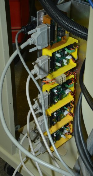
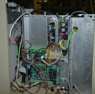
So stuff has been organized to the point of even adding labels to the DB25 cables, interface boxes and servo drives. The encoder signals from the motors go in one direction and the motor drive signals travel around on the other side of the machine before they come back together at the drives. To avoid coupling motor noise into the encoders as much as possible.
The Servo drives are temporarily up on the wall until I build a real insulated wall. Then they will go in some sort of cabinet. But for now it's all nicely organized.
Need to put a little box around the encoder interface wiring so that it's not hanging out in the open.
Then to finish off the draw bar now that the X axis should be once again repeatable.
Attachments
The Servo drives are temporarily up on the wall until I build a real insulated wall. Then they will go in some sort of cabinet.
You lost me with this statement???
In my Organized-1.jpg you can see the servo drives up on the wall and below that concrete. I need to insulate the entire closed in carport. Way too much humidity and rust over the last few years.You lost me with this statement???
Originally I wanted the entire control system in this cabinet.

Now it no longer fits. I'd have to almost start over. Don't really want to do that. But also don't want all those cables all over the place.
However, before I do anything I'd like to finish the power drawbar and then convert to ball screws and maybe even an automatic tool changer. So at the moment I have to live with the 4 Servo drives on the wall and the STMBL AC servo controller for the Harmonic drive A Axis inside the cabinet.
Since it's almost a year later and I've posted onto a few other threads I'll just update this conversion conversation with a summary update.
The power draw bar is not yet finished and will remain until the 25:1 planetary reduction drive shows up. In hindsight should probably have ordered 100:1 but I don't have an extra $100 to throw at another one.
Last year I started thinking about the ball screw conversion. One conversion will be the knee.
Currently there is a bevel gear on the end of the ACME screw which is turned by the horizontal shaft which is coupled to the 750W knee motor.

I saw a model on the web with a rotating ball nut to turn a fixed lead screw. That seemed like a good idea for the knee. Then the knee motor can sit vertically and turn a larger pulley that turns the ball nut.

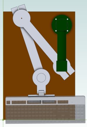
Exploded out

The ball nut is the dark grey part and it's firmly fastened to the blue part which is suspended in the bearings. The pulley is also bolted to the blue part and the pink housing is bolted to the pillar. Now turn the pulley and as long as the top end of the ball screw is prevented from turning it will move up and down taking the knee with it.
This is the plan. Still open to revisions.
The power draw bar is not yet finished and will remain until the 25:1 planetary reduction drive shows up. In hindsight should probably have ordered 100:1 but I don't have an extra $100 to throw at another one.
Last year I started thinking about the ball screw conversion. One conversion will be the knee.
Currently there is a bevel gear on the end of the ACME screw which is turned by the horizontal shaft which is coupled to the 750W knee motor.
I saw a model on the web with a rotating ball nut to turn a fixed lead screw. That seemed like a good idea for the knee. Then the knee motor can sit vertically and turn a larger pulley that turns the ball nut.
Exploded out
The ball nut is the dark grey part and it's firmly fastened to the blue part which is suspended in the bearings. The pulley is also bolted to the blue part and the pink housing is bolted to the pillar. Now turn the pulley and as long as the top end of the ball screw is prevented from turning it will move up and down taking the knee with it.
This is the plan. Still open to revisions.
Well rats! No procrastination allowed.
Ordered on the 25th of August with an October delivery date (although $30 shipping seemed high) the 25:1 planetary drive for the draw bar arrived this afternoon the 2nd of September.
Also the 8mm hand reamer ordered on the 22nd and yesterday, also ordered on the 22nd the two ER32 collet holders: hex and square.

All in excellent condition and well packed.
Ordered on the 25th of August with an October delivery date (although $30 shipping seemed high) the 25:1 planetary drive for the draw bar arrived this afternoon the 2nd of September.
Also the 8mm hand reamer ordered on the 22nd and yesterday, also ordered on the 22nd the two ER32 collet holders: hex and square.
All in excellent condition and well packed.
So threw together a quick sketch on how I might connect to a socket from a shaft that is 14mm diameter with a 5mm key.

In order to drive the 19mm socket and be able to broach a key way in the driver my approach is to do it in two parts. The first part is a simple hub with a key way and set screw hole to clamp onto the key along with a registration recess to center the drive hub.

It has 4 holes threaded 4mm to accept 4 screws through the socket drive part. This part could also have a hole drilled through the 3/8" part to pin the socket to the drive so it won't fall off.

Is this too complicated? Is there a simpler way perhaps? The only issue I see is that the 3/8" drive part isn't hardened. But then it's also not used as an impact driver. Will 20 ft-lbs of torque shear it?
Suggestions are welcome.
In order to drive the 19mm socket and be able to broach a key way in the driver my approach is to do it in two parts. The first part is a simple hub with a key way and set screw hole to clamp onto the key along with a registration recess to center the drive hub.
It has 4 holes threaded 4mm to accept 4 screws through the socket drive part. This part could also have a hole drilled through the 3/8" part to pin the socket to the drive so it won't fall off.
Is this too complicated? Is there a simpler way perhaps? The only issue I see is that the 3/8" drive part isn't hardened. But then it's also not used as an impact driver. Will 20 ft-lbs of torque shear it?
Suggestions are welcome.
Not an engineer, but have made thousands of 9mm square drive shafts for valves. Designed to ISO 5211, a 9mm square machined drive is rated with mounting flange F03 minimum 32nm, 283 in-lbs. Never had one break.
F03 is 36mm bolt circle. If you go up to a F05 50mm bolt circle you could support 125Nm torque.
Your failure point will be the four mounting bolts, not the 3/8” drive shaft.
ISO 5211
F03 is 36mm bolt circle. If you go up to a F05 50mm bolt circle you could support 125Nm torque.
Your failure point will be the four mounting bolts, not the 3/8” drive shaft.
ISO 5211
Thank you! Perfect. Great document.Not an engineer, but have made thousands of 9mm square drive shafts for valves. Designed to ISO 5211, a 9mm square machined drive is rated with mounting flange F03 minimum 32nm, 283 in-lbs. Never had one break.
F03 is 36mm bolt circle. If you go up to a F05 50mm bolt circle you could support 125Nm torque.
Your failure point will be the four mounting bolts, not the 3/8” drive shaft.
ISO 5211
I was actually going to use 5mm screws because I have lots after I went on a buying binge last year.
Although F03 is just on the edge of the motor/reduction drive combination (and torque requirements) going F04 is probably a bit safer.
But I also don't have any steel on hand that can be turned to 54mm diameter (or 46mm for F03) I'll have to check metal supermarket tomorrow morning I guess and see if they have some round 2.25" in stock.
John