-
Scam Alert. Members are reminded to NOT send money to buy anything. Don't buy things remote and have it shipped - go get it yourself, pay in person, and take your equipment with you. Scammers have burned people on this forum. Urgency, secrecy, excuses, selling for friend, newish members, FUD, are RED FLAGS. A video conference call is not adequate assurance. Face to face interactions are required. Please report suspicions to the forum admins. Stay Safe - anyone can get scammed.
-
Several Regions have held meetups already, but others are being planned or are evaluating the interest. The Calgary Area Meetup is set for Saturday July 12th at 10am. The signup thread is here! Arbutus has also explored interest in a Fraser Valley meetup but it seems members either missed his thread or had other plans. Let him know if you are interested in a meetup later in the year by posting here! Slowpoke is trying to pull together an Ottawa area meetup later this summer. No date has been selected yet, so let him know if you are interested here! We are not aware of any other meetups being planned this year. If you are interested in doing something in your area, let everyone know and make it happen! Meetups are a great way to make new machining friends and get hands on help in your area. Don’t be shy, sign up and come, or plan your own meetup!
You are using an out of date browser. It may not display this or other websites correctly.
You should upgrade or use an alternative browser.
You should upgrade or use an alternative browser.
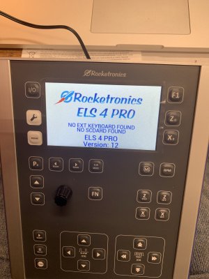
Electronic lead screw ELS - Rocketronics solution on Modern Tool C0636 lathe
- Thread starter Janger
- Start date
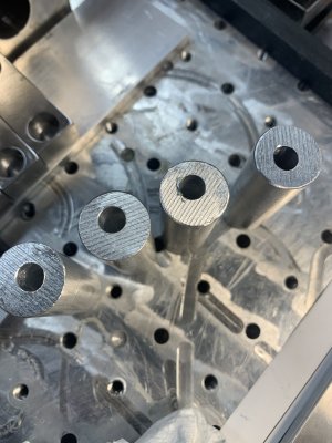
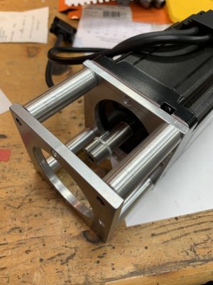
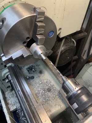
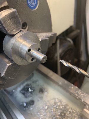
I’m making the round stand offs to separate the two plates above. Naively just drilling straight through resulted in crooked holes. See pic. So I rigged up the er32 collet block and drilled half way with a 1/4EM instead. Then flipped and did other end. It’s much better. It is 11x deep the bore diameter so kinda deep but not crazy. It’s a bit of pain as I end up pecking a lot. How do people do this productively?
Attachments
Last edited:
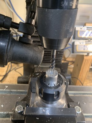
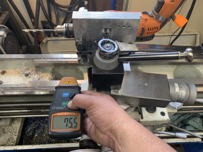
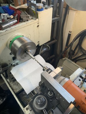
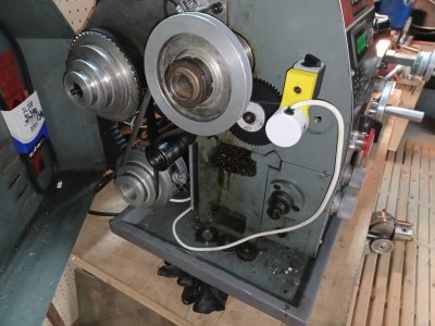
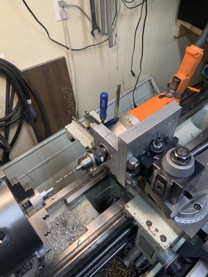
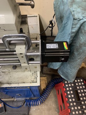
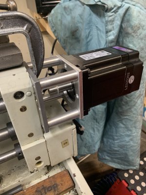
Standoffs again. Mr John Nielsen @johnnielsen suggested I gun drill (is that what this is called?) the standoffs with a lot of pecks and lots of oil. Well I made one standoff now and at the far end of 2.1" drilling the hole is 0.005" out or shifted crooked to the side of the part. That seems pretty good to me. I ran the drill at 800rpm with no load clock wise to match the 800 rpm on the lathe which is going counter clockwise of course.
I bought a pedal foot switch to run the drill and you can see I've got the plastic 3d printed wing nuts going on the drill hose clamp to set the drill speed.
Thanks @johnnielsen that made a very straight and true hole. 3 more to go...
I bought a pedal foot switch to run the drill and you can see I've got the plastic 3d printed wing nuts going on the drill hose clamp to set the drill speed.
Thanks @johnnielsen that made a very straight and true hole. 3 more to go...
Attachments
Last edited:
RobinHood
Ultra Member
Maybe a carbide drill bit? Should be stiffer than HSS and, if the cutting edges are sharpened precisely, should drill a straight hole. HSS with good and equal edge geometry should work.
But gun drill is certainly the best way to produce deep holes as @johnnielsen advises.
In your situation, a drill & bore operation might be tricky because of the hole dimensions...
Good solution in the end with lathe & drill motor.
But gun drill is certainly the best way to produce deep holes as @johnnielsen advises.
In your situation, a drill & bore operation might be tricky because of the hole dimensions...
Good solution in the end with lathe & drill motor.
With a length of 2.1" I would have held it in a collet chuck for concentricity, drill one side a bit more than half through, flip & drill the other to connect. Common issues for drifting drill
- drill not centered (TS off or collet block off in mill mode)
- drill edge geometry unequal causing pull/drift (use a fresh drill or anyways equally sharpened lands)
- too long a drill (use a stubby which is more rigid) & (drill half way on either side as mentioned)
- use a spotting drill with included angle >= drill angle (example 120-deg spot for 118-deg drill). Not a 60-deg countersink type drill like our shop teacher taught us
- oil & pecking & chip removal is always a good strategy
- if push comes to shove & you use EM, or carbide EM for even more stiffness, you still have to be aware of tip geometry. Sometimes its still better to drill undersize pilot hole even if it is off, but the EM cutting is not getting bogged down in the center. They are intended for plunging but not really drilling or deep drilling. They don't have any taper & you may run out of cutting edge vs depth. Carbide is hard & may tend to slip in chuck jaws but that's a side issue.
Anyway you got-r-done
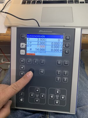
Hi @gerritv on your install did you keep use of the hand wheels for manual ops? For the Z axis (back/forth on spindle axis direction) I can just disconnect the thread / leadscrew engagement and then use the handles. But for the cross slide the motor will always be engaged. Did you do anything different to prevent the motor from sending back current into the rocketronics control? like installing a switch to disengage the motor?
Another possible problem I don't see in the manual yet - what about the lathe turning the lead screw and the rocketronics trying to do the same thing at the same time?
Another possible problem I don't see in the manual yet - what about the lathe turning the lead screw and the rocketronics trying to do the same thing at the same time?
Another possible problem I don't see in the manual yet - what about the lathe turning the lead screw and the rocketronics trying to do the same thing at the same time?
I would think you either remove the drive gear from the lathe or you disengage the feed lever. No way they can both be used at the same time without breaking something.
gerritv
Gerrit
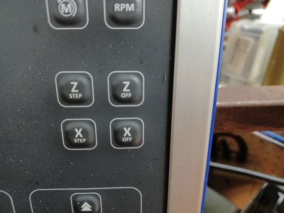
The control has Z Off and X Off buttons to disable each axis motor. I manually use the X axis once motor is off. (aso saves heating from the motor drivers). Detent every 1.8° due to stepper of course.
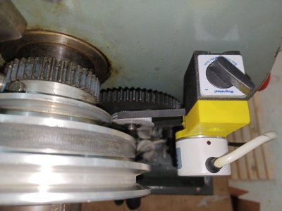
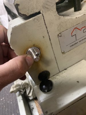
To avoid risk of lathe driving my leadscrew I removed most of the gear train. There must be a key gear that you can remove on your lathe?
To avoid risk of lathe driving my leadscrew I removed most of the gear train. There must be a key gear that you can remove on your lathe?
Attachments
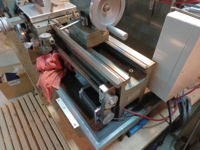
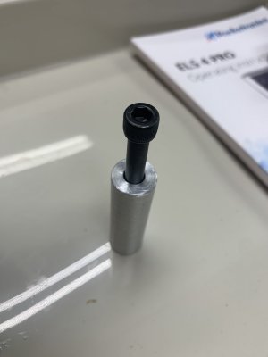
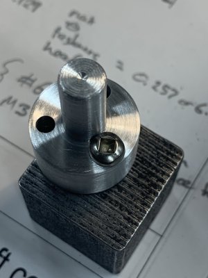
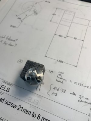
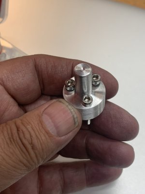
I made the lead screw to drive shaft adapter today. Used the tool post mounted drill fixture. Smaller than I expected little thing. #6 screws because I don’t have any M3 in house. Or wait maybe I do….
Attachments
-
 8741BE7E-174C-4CED-92AC-90B2C252F32C.jpeg273 KB · Views: 80
 -
 5E313912-29F7-461A-82EA-3CAACF217CD2.jpeg270.3 KB · Views: 46
 -
 93692B48-B0A6-4215-8F77-D694F8303A85.jpeg150.1 KB · Views: 78
 -
 E048B685-BE06-4B08-8688-9F05F95914F5.jpeg398.4 KB · Views: 46
 -
 4B9AEB13-29F0-4DDC-8E59-03C202E65094.jpeg470.2 KB · Views: 70
 -
 EA85E590-C516-47EB-829D-D8FA01FF8B1A.jpeg262.8 KB · Views: 76
TorontoBuilder
Sapientia et Doctrina Stabilitas
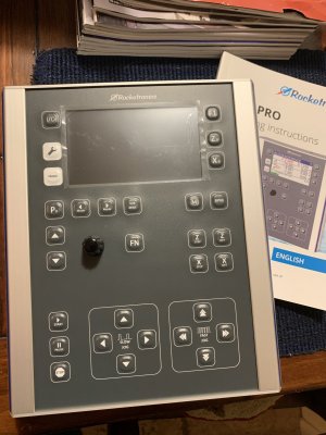
Is your rocketronics system installed yet?Mine was shipped in 2 boxes but he forgot to tell me the tracking # for the second one.
TorontoBuilder
Sapientia et Doctrina Stabilitas
gerritv
Gerrit
yes, been using it for a few months on a 10x22 lathe. Very pleased. Let me know what you want demo'd for your upcoming visit so I can get it set up ahead of time 🙂Is your rocketronics system installed yet?