• Scam Alert. Members are reminded to NOT send money to buy anything. Don't buy things remote and have it shipped - go get it yourself, pay in person, and take your equipment with you. Scammers have burned people on this forum. Urgency, secrecy, excuses, selling for friend, newish members, FUD, are RED FLAGS. A video conference call is not adequate assurance. Face to face interactions are required. Please report suspicions to the forum admins. Stay Safe - anyone can get scammed.

CT 043 issues ..... Repairs - Completed !!

I had a little break in the action today and poked around on the Craptex Lathe .

I can only take short intervals of this , I get flustered and walk away , also , I was having trouble with one of my multimeters , this has been going on throughout the entire process of trying to figure out what the hell is wrong with this P.O.S. , for weeks , adding to the frustration.

Todays observations..................

The motor is off the machine right now , both motors are resting , side by side on the bench to be looked at maybe tomorrow .

I spoke with a guy who is a master electrician , he repairs all kinds of industrial equipment , he's quite busy and it might be two weeks before he can have a look .

I've been using an older multimeter for testing , an OTC , it seems to have a mind of it's own and trying to get into the correct range is a pain in the butt , just when you think you are there it starts going crazy , looking at the label on the back tells me it's more crap from China ........... I used to use that meter a lot and liked it , not so much now.
I have a very nice Snapon meter at work that I enjoy using , it's at work though .
I went out to the motorhome and got another multimeter ( DiLog) which scrolls between ranges perfectly and doesn't pick up any transient interference from the fluorescent lights in my shop , this is a meter I've had over thirty years and it still works great .
I was able to actually get some measurements off the contactors and observe the behavior of them . The KM1 contactor is for reverse as I initially thought , that's the one with the thermal overload relay connected to it . When you select reverse with the switch on the carriage , it clicks and you can see with the meter that it is doing it's job . The contactor beside it , KM 2 doesn't click at all and appears to be toast , I believe that one is for forward . The funny thing with KM 2 is , when this whole episode began weeks ago , it would click & throw a few sparks around when you tried to select forward with the switch on the carriage , now it's dead .
KA contactor clicks when the lathe has power and stays that way , the funny thing with that one is , you can kill the power to the lathe , unplug it and that contactor remains in the closed position , eventually it clicks and opens up , like , an hour or so later , when I stopped farting around with the lathe and switched to doing other work I had going on , I heard it switch off when I happened to be standing there. This happened to me as well ,the other day when I was tinkering with it and walked away , a short time later I heard a click , it was KA contactor opening up .

I got a new thermal overload relay off of ebay , it came from China , arrived way ahead of what I had expected or what they had projected as a shipping time. this part is sitting off to the side with the start & run capacitors I bought from Amazon.
This morning I ordered three of the correct contactors off ebay , those are shipping from China .
I reached out to the company in Concord Ontario where the first set of contactors came from to see if I could return them , they've been paid and must not care and it's been a week without them returning my email.

I worked on it for an hour or so calmly and then moved on to other more stimulating stuff I have going on. Using an actual working multi meter today was almost like a breakthru !!

Tomorrow is a new day , I'll mess with it some more
 
Last edited:
Did you ever test the original capacitors against their stated rating? I happen to be talking to motor shop in Calgary & they said they routinely test capacitors for customers. I'm not sure if that meant more specialized equipment beyond the typical meter. But he said they often see problematic caps that are A) degraded B) not up to their own stated specs C) sometimes undersized for the duty they see. My own limited experience is if they are in that grey zone of not-quite-pooched it can drive you nutty chasing other likely issues.
 
Did you ever test the original capacitors against their stated rating? I happen to be talking to motor shop in Calgary & they said they routinely test capacitors for customers. I'm not sure if that meant more specialized equipment beyond the typical meter. But he said they often see problematic caps that are A) degraded B) not up to their own stated specs C) sometimes undersized for the duty they see. My own limited experience is if they are in that grey zone of not-quite-pooched it can drive you nutty chasing other likely issues.
No , the reason is , I don't have a clue how to do that.
 
I think ideally your meter should have a capacitance mode setting. The other modes are more indirect? Smarter electrical guys than me can chime in on this video. I've heard the screwdriver bleed off is not great for them but not sure what other options would be advised. Maybe some kind of resistance but above my pay grade. That's why I was suggesting a shop could check it. If it wasn't for one that blew not far from my head maybe I would be braver with my advise. My shorts were the same color as what leaked out of the cap HaHa,

 
Here is a link to a post I provided earlier

Post in thread 'Craftex CX709 motor issue?' https://canadianhobbymetalworkers.com/threads/craftex-cx709-motor-issue.4361/post-59368
The meter I'm using now has a capacitance test function on the dial . This meter was a knock off of a Fluke back in 1990 ish , it was in my tool box in the motorhome , stashed there incase I need it.

Part of the kerfuffle with trying to find the lathe problem was me not using a meter that works properly and not having any experience with AC motors n' contactors .
 
I had wired a switch (used) like this into my Logan lathe. And a primary start stop switch (later), put both in at the same time.

Reason A/C motors don't like sudden reverses, when you switch off and accidentally over shoot the off position......don't ask how I know :rolleyes:.

Set direction first with direction switch, start/stop via start/stop switch (mines a simple toggle switch, no access to fancy switches at the time).
 
Reason A/C motors don't like sudden reverses, when you switch off and accidentally over shoot the off position......don't ask how I know
Unless you have a 3ph and VFD. On the fly direction changes become a piece of cake with no adverse consequences that I know of.
 
KM2 sounds like the contactor welded itself closed at the high voltage contact points.
Quite likely , I'm gonna give it another look today before I work on other stuff that I actually like doing.

Also , It's possible that because of the welded / damaged contactor The new motor may be damaged too .

I'll be removing the electrical box again today after I do some more checking with my meter , it's way easier working on it on the bench .

I've got a cool project going that doesn't require the use of a lathe , I've managed to work around this P.O.S. being down but there is a list of stuff to do once it's running again.
 
These dinky little contactors do not come apart easily , I'm going to just change them and start fresh . I have three ordered from the land of China .

Finding this stuff locally or in Canada is a crapshoot , no one has any of it .

The manager at BBT told me " you can't expect us to stock parts for a machine that old " which I saw as a semi polite way of blowing me off , the lathe that replaces this one is a CX 707 , it probably has the exact same components and layout inside the electrical box , I was unable to confirm that though , they have another lathe shoved up against the back of it so you can not have a look , you should have seen the glare I got for suggesting we move it so I could look inside. The manual for the CX 707 does not include a wiring diagram.

The fact that they were un willing to help me sends a pretty clear message , anyone who buys this stuff is on their own if anything goes wrong , they do not have parts and they do not have anyone on staff that has the depth or customer service savy to deal with technical problems.
 
This is exactly what I feared originally and why I never just replace a motor without checking an entire energizing circuit for issues first.

Fir our last move we removed the lathe motor. We got the lathe moved and reassembled except for mounting the motor again. It is a pig to mount due to the manner the pivot pins have to be aligned where there is little room to access them. I wasn't able to attend the shop on one of the following day so my brother did this himself.

He couldn't get the lathe to run when reassembled. Or rather the lathe was functioning intermittently after reassembly and instead of properly diagnosing things like I would he just pushed contactors in. In doing so our lathe motor "toasted". Doing so overrides the safety interlock between KM1 and KM2.

Welded contactor points are common enough it should be one of the first inspections. A simple continuity test will save a lot of grief.
If I'da known at the beginning This could have been resolved more quickly , that and using an actual working multimeter from the start would'a been beneficial.
 
In the process of working my way through this I was not pleased with the wiring diagram provided by BBT , it pissed me off , I do not think clearly when I'm pissed off.
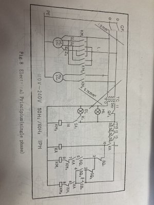
This is the one in the owners manual , Fig 8 "Electrical Principium " is what they call it , what a joke !.
IMG_1455.JPG

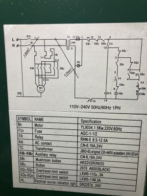
This is the one inside the electrical box , on the door .

Schematic inside electrical box.jpg
The drawings above are almost useless , anyone who has purchased a CX707 is on their own to figure any of this out.
There's no master power switch , for over 18 years , I've been just plugging it in and using the breaker to power it up. There's so much missing from both of the diagrams they provided , I was confused from the start , I always thought I had a good handle on electrical , well , automotive / mobile equipment / low voltage systems anyways.


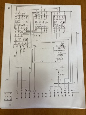
I've made my own drawings , this is the only way I can get my brain around how this thing is wired . I'm working on a second diagram , detailing the "e" stop , power lamp , jog button & the switches on the carriage . In my day to day activities as a mechanic , it's how I have been able to successfully complete repairs , by having an actual wiring diagram to work with. The wiring diagram inside the door and in the owners manual are not even close to being helpful .

IMG_1514.JPG
 
Last edited:
Back
Top