Cross-Slide Leadscrew & Nut

thestelster

Ultra Member
Premium Member
Here is a couple of thoughts:

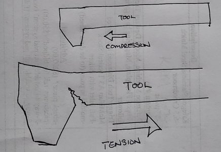
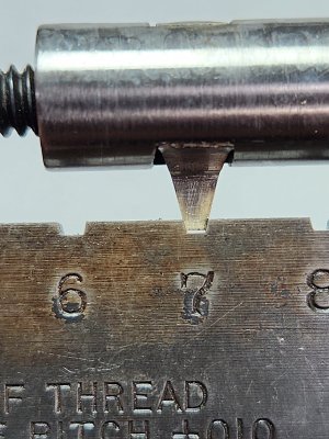
Moving the tool in the one direction the forces acting on the cutter is compressive.

Going in the other direction the forces on the cutter is tension. And breaks at the corner. Plus carbide is very brittle as we know.

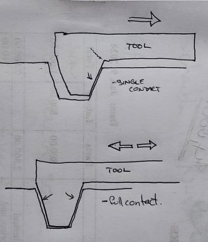
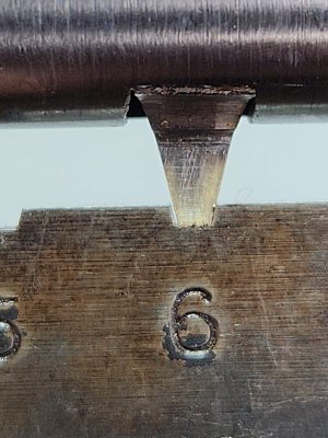
When I was plunging into the work, the threading tool is completely supported on the leading and trsiling edges.

But when I started to move axially, it created a gap at the trailing edge which allowed the cutter to flex at that inside corrner of the tool.
 

Attachments

  • 20240313_070457.jpg
    20240313_070457.jpg
    287.8 KB · Views: 6
  • 20240313_070137.jpg
    20240313_070137.jpg
    324.3 KB · Views: 6

Susquatch

Ultra Member
Administrator
Moderator
Premium Member
Maybe, internal threading right hand, external threading left hand. This way the cutter is always moving in the one direction.

Makes some sense. Doesn't explain how it survived the initial phase of cutting the thread though.
 

Susquatch

Ultra Member
Administrator
Moderator
Premium Member
But when I started to move axially, it created a gap at the trailing edge which allowed the cutter to flex at that inside corrner of the tool.

My assessment says otherwise. I believe you are right about the bending that takes place as well as the stress riser at that inside corner. However, I don't think the outer edge compensates for the inner edge. I think it adds to it. BOTH edges cause bending in the same direction. I also don't think the outer edge constrains the bending during the plunge cut. Again, I believe it is additive.

Lastly, I don't think we should forget that the dominant forces are always going to be the downward deflection of the tool caused by the rotating part forcing the top of the tool down. Sideways forces are only a tiny fraction of that force.

I am still plagued by that one photo you took which appeared to have a nose on the tool that might have been rubbing.

A wild assed theory might be that the tool bent enough from the combined cutting forces to clear the face, but with less cutting force it didn't bend enough to clear and this setup conditions for Rubbing chatter. Again a wild theory.

HSS would be way better at resisting this twisting force.
.
 

thestelster

Ultra Member
Premium Member
My assessment says otherwise. I believe you are right about the bending that takes place as well as the stress riser at that inside corner. However, I don't think the outer edge compensates for the inner edge. I think it adds to it. BOTH edges cause bending in the same direction. I also don't think the outer edge constrains the bending during the plunge cut. Again, I believe it is additive.

Lastly, I don't think we should forget that the dominant forces are always going to be the downward deflection of the tool caused by the rotating part forcing the top of the tool down. Sideways forces are only a tiny fraction of that force.

I am still plagued by that one photo you took which appeared to have a nose on the tool that might have been rubbing.

A wild assed theory might be that the tool bent enough from the combined cutting forces to clear the face, but with less cutting force it didn't bend enough to clear and this setup conditions for Rubbing chatter. Again a wild theory.

HSS would be way better at resisting this twisting force.
.
Yeah, I honestly don't really know what happened. Nonetheless, I'll be making a new tool today from HSS attached to a boring bar.

Hopefully I can find the broken piece and examine it closely and maybe silver solder back together and only use it for RH threading.
 

jcdammeyer

John
Premium Member
Yeah, I honestly don't really know what happened. Nonetheless, I'll be making a new tool today from HSS attached to a boring bar.

Hopefully I can find the broken piece and examine it closely and maybe silver solder back together and only use it for RH threading.
Do you have one of these? With it you can grind the bit to the exact profile.
1710349087562.png
 

thestelster

Ultra Member
Premium Member
Do you have one of these? With it you can grind the bit to the exact profile.
View attachment 45529
Yes, I just got one a couple weeks ago.

I've been grinding my bits by setting the angles with a sine vise for clearance angles, and a 14.5° angle plate for thread form.

But that gauge comes in handy to set the tool up on the lathe, and checking acme thread size.
 
Last edited by a moderator:

thestelster

Ultra Member
Premium Member
The crossfeed screw nut is threaded.

After the solid carbide threading tool snapped, I didn't want to order another one, because it might have met the same demise. So I decided to make one using an existing cheap 1/2" boring that I had. Of course, I had to reduce the diameter of the bar to 3/8" for about 2" long.

It takes 3/16" hss bits. So I ground one down for acme threads. It is a little smaller than 6 tpi, and a little larger than 7tpi, so lets call it 6.5tpi.

Plunged to major diameter and then advanced the compound 0.002" per pass to open up the thread to a 5tpi. Thickness of a 5tpi thread at pitch diameter is 0.100", at 6.5tpi it's 0.077". The difference is 0.023". This is approximately the distance I have to move the compound to get a 5tpi acme thread profile.

I got there and it was just a little too tight. Moved another 0.001", and several spring passes and it's a perfect fit. No perceivable play, and ever so slightly tight at one section of the new cross-slide screw.
 

Attachments

  • 20240313_104355.jpg
    20240313_104355.jpg
    671.4 KB · Views: 11
  • 20240313_105154.jpg
    20240313_105154.jpg
    601.8 KB · Views: 10
  • IMG_20240315_124217.jpg
    IMG_20240315_124217.jpg
    291.5 KB · Views: 10
  • IMG_20240318_135959.jpg
    IMG_20240318_135959.jpg
    359.3 KB · Views: 10
  • IMG_20240318_140144.jpg
    IMG_20240318_140144.jpg
    454.4 KB · Views: 9
  • 20240318_140452.jpg
    20240318_140452.jpg
    383.5 KB · Views: 10
  • 20240318_140532.jpg
    20240318_140532.jpg
    279.2 KB · Views: 10
  • 20240318_134231.jpg
    20240318_134231.jpg
    407.5 KB · Views: 10
  • 20240318_140801.jpg
    20240318_140801.jpg
    478.2 KB · Views: 10

Susquatch

Ultra Member
Administrator
Moderator
Premium Member
I got there and it was just a little too tight. Moved another 0.001", and several spring passes and it's a perfect fit. No perceivable play, and ever so slightly tight at one section of the new cross-slide screw.

Looks great Stel! I would have just ground a HSS Boring bar, but I can see clear advantages to using a small bit in a boring bar if you have the room.
 
Last edited:

Susquatch

Ultra Member
Administrator
Moderator
Premium Member
Nice. But why not just make the tool fit the 5 TPI guage?

I think he is just playing it safe. Too much to bite off in one go. Better to cut with a smaller blade and then cut sideways to the full tooth profile.

Heck, if it was me I might have only cut a V with no nose. In fact, maybe just a trailing edge at 55 and 90 on the leading edge and then cut sideways with another ground tool.

I'm not a fan of big huge cuts even if my lathe can do it. I have all day, so I like to enjoy the time and work carefully and wisely. I'm in no rush to git er done!
 

thestelster

Ultra Member
Premium Member
Finished. All assembled. There is app. 0.002" backlash. So, I'm pretty happy.

What an ordeal this was!! Now to do some real work and make money.
 

Attachments

  • 20240318_182528.jpg
    20240318_182528.jpg
    462.9 KB · Views: 9
  • 20240319_074138.jpg
    20240319_074138.jpg
    470.8 KB · Views: 9
  • 20240319_104929.jpg
    20240319_104929.jpg
    559.4 KB · Views: 7
  • 20240319_105022.jpg
    20240319_105022.jpg
    534.2 KB · Views: 7
  • 20240319_123216.jpg
    20240319_123216.jpg
    814.7 KB · Views: 7
  • 20240319_124813.jpg
    20240319_124813.jpg
    592.4 KB · Views: 7
  • 20240319_124847.jpg
    20240319_124847.jpg
    617.2 KB · Views: 7
  • 20240319_150950.jpg
    20240319_150950.jpg
    582.5 KB · Views: 8
  • 20240319_161848.jpg
    20240319_161848.jpg
    427.5 KB · Views: 8
  • 20240319_161927.jpg
    20240319_161927.jpg
    548.3 KB · Views: 10

Brent H

Ultra Member
@thestelster : nice work!!! Those Utilathes and their nuts!! Doing the Internal threading leaves for a lot of tool holder flex and I found I had to let the tool ride through many clearance passes and test fit frequently to get a great final fit. I also held pressure on the boring bar during the cuts ….

You also need a lot of back grind on the tool bit to make sure there is no friction only cutting. Sorry for the late chime in - might have helped with some aggravation! But, mine were laundry room tiles - LOL. Nice work as always!
 

thestelster

Ultra Member
Premium Member
I also held pressure on the boring bar during the cuts ….
How did you do that? The boring bar I used was a not hardened, and I turned a 2" section down to 3/8", so that's more than 5:1 L/D. I had to do a number of spring passes when I was getting close to final dimension.
 

Brent H

Ultra Member
Well……I used a finger o_O 
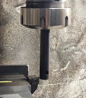
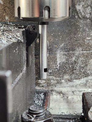
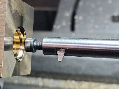
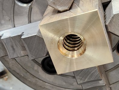
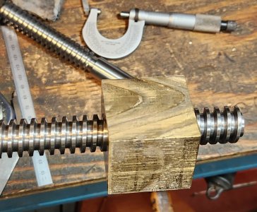
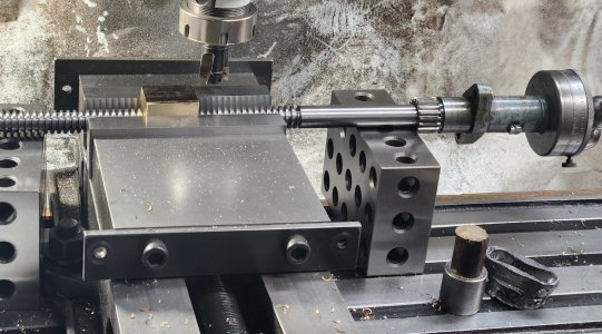
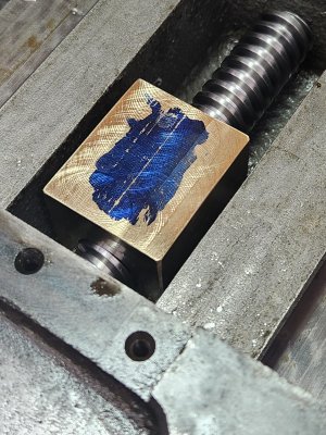
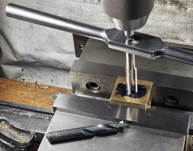
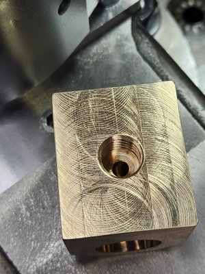
Just at the end of the cut. Also boring bar held at bare minimum length for max support at the thread length. I was threading 9/16” LH acme for my smaller Utilathe. The cutter was quite undercut to allow the back clearance.

I think I had a bit of an ACME threading thing on the restoration of the Cincinnati tool sharpener? Anyway, hoping to have the machines running end of this weekend again and then the
Memories can (hopefully) come flooding back -
LOL
 
Top