• Spring 2024 meetup in Calgary - date Saturday, April 20/2024. discussion Please RSVP Here to confirm and get your invitation and the location details. RSVP NOW so organizers can plan to get sufficient food etc. It's Tomorrow Saturday! you can still RSVP until I stop checking my phone tomorrow More info and agenda
  • We are having email/registration problems again. Diagnosis is underway. New users sorry if you are having trouble getting registered. We are exploring different options to get registered. Contact the forum via another member or on facebook if you're stuck. Update -> we think it is fixed. Let us know if not.
  • Spring meet up in Ontario, April 6/2024. NEW LOCATION See Post #31 Discussion AND THE NEW LOCATION

Craig's Craftex CX706 Comes Clean

trlvn

Ultra Member
Reviving an old thread because I finally got around to looking into some nagging tailstock issues with my CX706 10X22 lathe. Note that the Precision Matthews 10 inch lathes (PM1022 and PM1030V) have the same design tailstock with a quick-lock lever. The manual from PM is a little better than the one from BusyBee, but not much.

What prompted me to look at the tailstock was that it wouldn't lock solidly on some areas of the bed. The tailstock would push backwards when I tried to drill a reasonable size hole.

Let me digress by saying that I made this a lot harder on myself than it needed to be because I installed the lathe with the tailstock end too close to a wall. There is not room to slide the tailstock off the end of the ways. Unbolting the lathe is a pain since it is shimmed to reduce the (minor) twist. Also, the bolts under the headstock are akward to get at. More on this when we get to reassembling the tailstock.

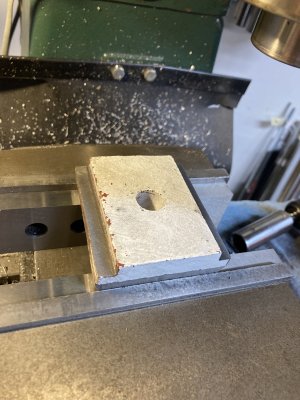
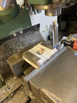
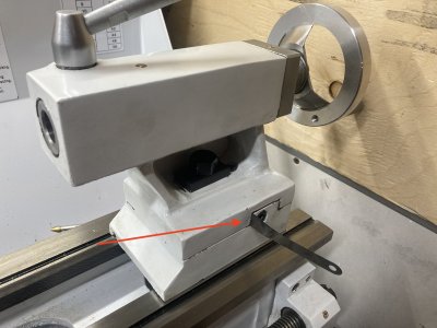
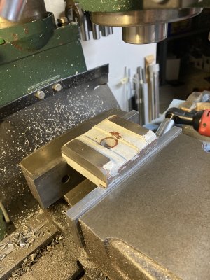
My clamping problem was mostly due to paint/filler on the clamp block (#36 on p.33 of the CX706 parts diagram). Sorry, I don't have a "before" picture. I used my mill to take a skim cut along the two surfaces that clamp up against the lathe bed.

IMG_4984 tailstock top.jpg

You might ask how I was able to hold this irregular shaped casting. I first set it up with the existing machined surfaces in the vice and used a fly cutter and end mill to make reference surfaces that were flat and parallel to existing clamping surfaces. See following.

IMG_4983 tailstock clamp bottom.jpg

(Cont.)
 

trlvn

Ultra Member
Now to reassemble the tailstock...this can't be hard, right? And it wouldn't be if I had room to slide it on from the end of the bed. Or if I had three to four really small hands. ;)

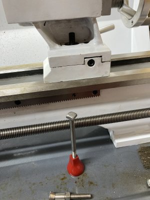
The clamping block needs to be held up against the bottom of the bed so there is room to start the nut underneath. However, I need to push down on the threaded stud from above because the spring is causing it to lift. Eventually I found that an extra long bolt in my machinist's jack under the clamping block would hold it up while leaving my hands free to get the nut started.

IMG_4986 tailstock jack.jpg

Note that there is a groove or slot cast into the underside of the clamping block. This captures the nut to prevent it from backing off after you get it set. The quick-lock lever is adjusted by this underside nut--a 1/6 turn of the nut is the difference between the lock working decently or being uselessly loose.

A digression about the nut on the top side. It has nothing to do with the quick-lock lever. If you only ever used the quick lock, you could leave it off entirely. If you wrench it down tight, then the tailstock will be locked and the quick-lock lever will do nothing. Seems like a weird design but that's the way it is. All I can think is that the quick-lock lever uses an eccentric shaft to provide the locking force. This shaft is not all that thick and it is possible that it could get bent due to ham-handed operation or even just over repeated use. The top side lock nut would allow the tailstock to be locked in the event that the quick-lock is destroyed. The top side nut probably also locks the tailstock more securely than the quick-lock lever is capable of. Why that would be necessary in normal use escapes me.

(Cont.)
 

trlvn

Ultra Member
Next step, of course, is to align the tailstock with the headstock. Here we get to experience the best of Chinese engineering. Screws (#33) are provided to pull the top part of the tailstock casting (#10) forward and back across the lower portion (#31). BUT, there is a 6mm locking set screw at the back (#28). The top portion of the casting bears against the lower portion on three points: the two 'ears' of the lower casting and the locking set screw.

When trying to adjust alignment, it is WAY too easy for the top and bottom portions of the tailstock to get 'cocked'. The locking set screw needs to be loosened to use the adjusting screws. But when I snugged up the locking screw, the tailstock then moved an additional amount that I didn't expect. Also, the adjusting screws are pretty coarse (M8X1.25) so even a tiny bump on the screw moves the tailstock alignment by a couple of thous.

I also noticed that the (dogpoint) locking set screw was chewing up the (softer) cast iron.

IMG_4982 tailstock base damage.jpg

I think this damage was causing the base to 'squirm' as I tightened the locking screw. I used a hone to smooth out the damaged section. I also made a tiny brass plug as a cushion between the screw and casting.

(Cont.)
 

trlvn

Ultra Member
But oh no, that's not all! While I was messing this trying to align the tailstock, I decided to check that the tailstock quill was aligned with the lathe bed. You guessed it, the answer was "NO". The quill was angled off toward the operator by about 2 thous over 2 inches. With some trial and error, I found that a 3 thou shim put the quill in alignment.

IMG_4988 shimmed tailstock.jpg

The final insult is that the tailstock does not lock down repeatably. For alignment, I use a ground test bar between centers that I'm confident is straight and concentric. After aligning the tailstock to essentially zero over the 10 inch length or the test bar, it moves if I unlock, move and relock the tailstock. Not that much but a full thou most of the time.

I think the remaining problem is the V-groove in the bottom of the tailstock base. (Sorry, no pic.) I noticed that the maching is not all that smooth. Certainly not like a ground surface. AFAICT, scraping in the groove to the corresponding inverted V on the bed would likely be the way to fix this remaining problem. Alas, I have none of the tools or supplies for scraping and certainly none of the needed skill. There isn't much material to play with, either. I believe the tailstock quilll is about 1/2 thou higher than headstock spindle.

Craig
 
Last edited:

CWret

Ultra Member
Premium Member
Reviving an old thread because I finally got around to looking into some nagging tailstock issues with my CX706 10X22 lathe.
You started this thread about the time I joined the Forum. Back then my interest was getting a mill, not a lathe. Now I’m thinking that acquiring a lathe may change from ‘I want one’ to ‘I need one’.
Also - the CX706 looks like a good choice.
So thanks - I’m glad you revived this thread. I’ve started back at the beginning.
Once you satisfy your want of a lathe, you will realize how much you have needed one for some time now....:rolleyes:
 

DPittman

Ultra Member
Premium Member
Now I’m thinking that acquiring a lathe may change from ‘I want one’ to ‘I need one’.
Oh yes if you have a milling machine then you definitely NEED a lathe.
Of course space and money are usually limiting constraints when choosing a lathe but I believe the 10x22 lathes are a good choice considering the cost and space they require.
 

whydontu

I Tried, It Broke
Premium Member
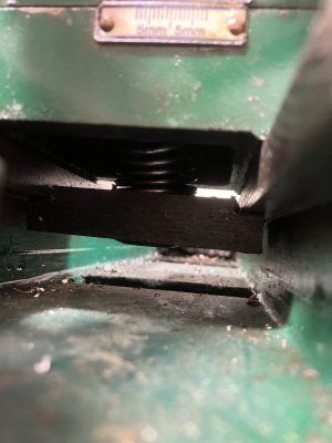
A suggestion, as your experience is quite a bit like mine on my BB B2227 lathe. On top of the issues you mention, I also found the tail stock would stick when moved, and if I loosened the lock enough to slide then the offset lock would loosen.

Big stiff spring between tail stock body and lock plate, keeps tension on the offset lock while giving positive thrust to release the lock plate.

IMG_3625.jpeg
 

trlvn

Ultra Member
AFAIK, I believe that is normal and allows for a little bit of wear on the tailstock. A little bit high won't make as much difference as it would if it was fore or aft.
Agreed. I was trying to point out that if I scrape the base, it is quickly going to be lower than the spindle height.

Craig
 
Last edited:

Susquatch

Ultra Member
Administrator
Moderator
Premium Member
Once you satisfy your want of a lathe, you will realize how much you have needed one for some time now....:rolleyes:

Don't know if I ever gave you my opinion of this one @CWret. As implied by @140mower & @DPittman, I have always been of the opinion that a pedestal grinder comes first, then a drill press, then a lathe, then a bandsaw, then a mill. I got the band saw out of order after the mill and regretted it.
 

trlvn

Ultra Member
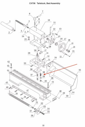
@whydontu If I understand correctly, I think the CX706 already has such a spring. See the following:

Tailstock parts diagram.jpg
It doesn't show very well, but the spring (#38) and washer go on top of the clamping plate ((#36). I wondered if the spring was really necessary but I guess your experience suggests it is?

Craig
 

Susquatch

Ultra Member
Administrator
Moderator
Premium Member
The clamping block needs to be held up against the bottom of the bed so there is room to start the nut underneath.

I do mine either of two ways.

1. I have the room to slide it off the end. I just have to remove a stop pin.

2. There is a big hole in my bed that I can reach through to hold the bottom clamp up with.

20240110_123742.jpg

On my lathe, you adjust the bolt so that the lever will almost but not quite go over center. This provides the required clamping leverage AND takes up any irregularities in the casting under the ways!
 

trlvn

Ultra Member
@Susquatch Yup, that is the same on the CX706 except the hole in the lathe bed is not much bigger than my hand. Also, the eccentric that the lever operates provides a really small movement. That's why a 1/6 rotation of the bottom nut is the difference between working or not!

Craig
 

DavidR8

Scrap maker
Administrator
Moderator
Premium Member
@Susquatch Yup, that is the same on the CX706 except the hole in the lathe bed is not much bigger than my hand. Also, the eccentric that the lever operates provides a really small movement. That's why a 1/6 rotation of the bottom nut is the difference between working or not!

Craig
Could you make a new stud with finer thread pitch on the bottom part?
 

trlvn

Ultra Member
Could you make a new stud with finer thread pitch on the bottom part?
Probably but I think they used locktite to secure #37 to #29. I guess heat would likely break that. OTOH, I would still need a 19 mm nut to fit the groove in the bottom clamp. Since I got it to work, I don't plan to go to that effort.

Craig
 

trlvn

Ultra Member
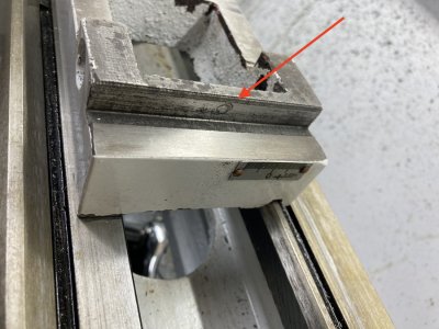
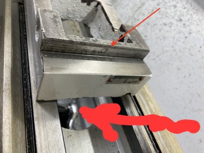
The stud for the bottom nut is 12mm diameter which I believe is 1.75mm pitch or about 0.069 inches per revolution. A 1/6 turn would be about 0.011 inches; 11 thous. The nut bears against a painted and unmachined surface:

IMG_4983 tailstock clamp bottom.jpg

As you can see, some of the paint is worn away and the red undercoat is visible. In some areas there was also a Bondo-like filler. That wear was probably a good part of the reason why my quick-clamp lever basically stopped working! The paint layer was would have been quite a few thous thick.

If I need to remove the tailstock again, I think I'm going mill down so the nut bears against clean metal.

Craig
 

slow-poke

Ultra Member
Not sure if you install your QCTP yet, but FWIW, I did it like this on a CX706


This CX706 upgrade might interest you......
..... https://www.hobby-machinist.com/threads/busy-bee-cx706-compound-mount-upgrade.88490/
 
Last edited:
Top