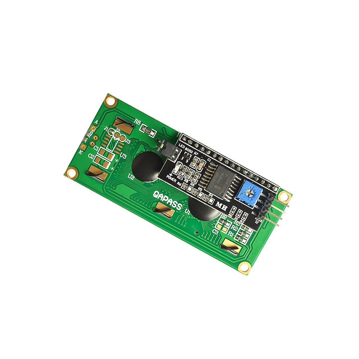
It is built a lot like yours using an Arduino Nano (with 16MHz ATMega328 CPU @ 16 MHz), a standard 16x2 LCD display with an I2C to parallel converter for the LCD.
View attachment 18809
The heat-shrinked device in the foreground is a constant current source for the LCD backlight. The LCD is a bit of an older device I've had around for a while that is unique in that it has larger than usual fonts (good for old eyes like mine), but uses the standard LCD parallel interface.. The disadvantage is that the LED backlighting uses old design LED's that are quite inefficient so it needed a special supply.
A design mistake is that I should have mounted the Nano with the USB port at the edge of the box with a hole. As it is, to re-program it, I have to open it up and use a 90 degree USB adapter to connect it to my laptop. On the other hand, I've only had to do that once since I found a bug after installing it, and will likely never update the code since it seems to work well.
The board is just perf board with point to point wiring on the back. A DC-DC converter takes 24VDC (that I had available in the lathe control circuitry) and brings it down to 5V that the Arduino and encoders are happy with.
The encoders are cheap units from Aliexpress: (something like:
https://www.aliexpress.com/item/1005002241818396.html - I don't remember exactly which ones I ordered), so nothing fancy.
It would be cool to interface an Arduino to my DRO Y-axis and use it to drive the VFD to achieve a semi-constant speed across a face like you are suggesting.
This has gotten me thinking that I need to build a simpler version of this for the mill giving RPM and feed rate for a cutter diameter.
I am willing to share my code (it also provides much of the project's detailed documentation), but I do not want to post it on a public forum. Send me a PM with an e-mail address and I will send it to you.
The front panel is created by back engraving a thin sheet of clear acrylic with a laser cutter. The acrylic has a layer of sliver and then black paint on it (I didn't coat it, I bought it like that). The lettering is then painted with a couple of colors of acrylic paint (stolen form my wife's art supplies) so the text shows up as colored text on the front, but does not have to be applied carefully. The clear window was engraved in the same way and then polished with a Dremel since the engraver leaves a matt finish in the acrylic.
View attachment 18810
The diameter control is a pot that is read with an AnalogRead(), and fed into a log function to make it non-linear so it can reasonably be used from 0.1 - 12".
It was all written using the Arduino IDE, but there is no official Arduino support for the ATMega328 pin-change interrupts (maybe there is a library, but I didn't really look for one and performance is really important there so I wanted to do it myself), so that is done by directly manipulating the CPU registers and writing the (very simple) interrupt functions.