• Spring 2024 meetup in Calgary - date Saturday, April 20/2024. discussion Please RSVP Here to confirm and get your invitation and the location details. RSVP NOW so organizers can plan to get sufficient food etc. It's Tomorrow Saturday! you can still RSVP until I stop checking my phone tomorrow More info and agenda
  • We are having email/registration problems again. Diagnosis is underway. New users sorry if you are having trouble getting registered. We are exploring different options to get registered. Contact the forum via another member or on facebook if you're stuck. Update -> we think it is fixed. Let us know if not.
  • Spring meet up in Ontario, April 6/2024. NEW LOCATION See Post #31 Discussion AND THE NEW LOCATION

Bridgeport Mill Tachometer

whydontu

I Tried, It Broke
Premium Member
I have a theremin that uses two US sensors that can differentiate movement of about 0.3cm. Off the top of my head, one US sensor, one trigger plate, take ten sets of absolute distance measurements, calculate the difference between closest and farthest, some math gets FPM. Wouldn’t be affected by the ram settings of start, end, or stroke. With some clever code it could calculate extend and retract speeds independently.

start
read distance1
wait time milliseconds
read distance2
if distance1>distance2 measurement is extend
if distance1<distance2 measurement is retract
subtract distance1 from distance2 = distancenet
make distancenet an absolute value
distancenet / time multiplied by conversion factor becomes FPM
display extend and retract values on lcd

this could be a real down-the-rabbit hole idea. Picture a relatively simple device with two dials - cutter diameter, number of flutes. Sensor to measure transverse speed of milling machine table. Sensor to read quill RPM. Some math gets display to show quill RPM, FPM of table, FPM of cutter.
 
Last edited:

Susquatch

Ultra Member
Administrator
Moderator
Premium Member
Hmmmm..... wrong thread, I think... https://canadianhobbymetalworkers.com/threads/rotary-table-questions.3941/ ?

Have you put that Bridgeport up for sale yet?

Ya, you guessed it. I'll delete it and repost in my rotary table thread.

No, not for sale yet. My wife and I are busy cleaning out my mother's condo. She has dementia and won't be going back so we have sold it and the closing date is next Wednesday.

After that, I hope to be able to clean the Bridgeport, paint it, and then post it for sale. I'm sure it will take longer than this makes it sound though.
 
Last edited:

Susquatch

Ultra Member
Administrator
Moderator
Premium Member
........
Have you put that Bridgeport up for sale yet?

Good catch.

Btw, my Arduino stuff arrived today. Lotta great stuff for so little cash......

Think I'll do what you did and just try a sample simple download for the sheer fun of it!
 
Last edited:

whydontu

I Tried, It Broke
Premium Member
First pass at adding a FPM function to my tachometer software.

Added a 10K pot, reading the pot position selects a cutter size from an array. For my machine, the size lookup array will be 1/16" to 1" by 1/16th, then 1-1/2", 2", and 3". I doubt I'm ever going to be running a face mill bigger than 3". My mill is a Busy Bee CT129, same as a Grizzly G0704

From cutter size and RPM it calculates real-time cutter FPM. I haven't uploaded it to my tach yet, just want to make sure it works before I start drilling holes in the case.

So instead of having a big chart with cutter size vs. material vs. RPM, all I'll need is a cheat sheet with suggested FPM vs. material. If I make a new slightly bigger tach case I could engrave the cheat sheet on the case.

If you're interested I'll send you the code once I have it finished.

IMG_1722.jpg
 

Susquatch

Ultra Member
Administrator
Moderator
Premium Member
First pass at adding a FPM function to my tachometer software.

Added a 10K pot, reading the pot position selects a cutter size from an array. For my machine, the size lookup array will be 1/16" to 1" by 1/16th, then 1-1/2", 2", and 3". I doubt I'm ever going to be running a face mill bigger than 3". My mill is a Busy Bee CT129, same as a Grizzly G0704

From cutter size and RPM it calculates real-time cutter FPM. I haven't uploaded it to my tach yet, just want to make sure it works before I start drilling holes in the case.

So instead of having a big chart with cutter size vs. material vs. RPM, all I'll need is a cheat sheet with suggested FPM vs. material. If I make a new slightly bigger tach case I could engrave the cheat sheet on the case.

If you're interested I'll send you the code once I have it finished.

View attachment 17721

This is super cool! I love it!

I have these charts on the wall behind my lathe that show graphs of fpm and material etc. I confess I rarely look at them as most of my work is pretty standard and I have a pretty good feel for what diameter does to fpm.

Still, how cool is that to be able to display fpm right on the tach display!
 

whydontu

I Tried, It Broke
Premium Member
yup. bog standard 16x2 LCD with I2C adapter. using the adapter means you only need two of the digital io ports to communicate. Without the I2C the LCD uses 5 io pins.
 

Susquatch

Ultra Member
Administrator
Moderator
Premium Member
yup. bog standard 16x2 LCD with I2C adapter. using the adapter means you only need two of the digital io ports to communicate. Without the I2C the LCD uses 5 io pins.

No worries. I ordered two displays and two I2C adapters to go with them.

I just liked the way it looked in your photo - especially with 2 lines of data. So I hoped that is what mine would look like too.
 

whydontu

I Tried, It Broke
Premium Member
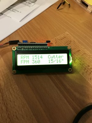
I got to play all day, SWMBO wanted to spend her day reading. Here's my current code, and photos of the device mocked up. I use a 10K pot to set the cutter diameter, values from 1/16" to 1" x 1/16", then up to 4" in larger jumps.

It's reading a signal generator for the RPM input. It's stable at an input signal of 180hz, equivalent to 10,000 RPM with a single reflective stripe on my mill quill.

At a simulated 10,900 RPM with the cutter selected at 1-1/2", it reads FPM at 4400. The math isn't perfect as I did it all in 2s-complement integers, but it's close enough for our uses. And nobody in their right mind is going to run an 1-1/2" cutter at 10K RPM.

I ran out of display characters, need at least 9 for RPM and at least 7 for FPM. so fpm is lower case because it was hard to read as RPM 2000 FPM800, RPM 2000 fpm800 was cleaner. spacing is easy to change, the lcd.setCursor commands will move the starting points for the lcd.Print commands. (column, row) starts at (0,0) at the upper left corner.

By gentle when you look at my code. I'm not a very good programmer, my older brother who is a great programmer calls me a script kiddy.

Code:

#include <Wire.h>
#include <LiquidCrystal_I2C.h>

// Set the LCD address to 0x27 for a 16 chars and 2 line display
LiquidCrystal_I2C lcd(0x27, 16, 2);
const int dataIN = 2; //IR sensor INPUT


unsigned long prevmillis; // To store time
unsigned long duration; // To store time difference
unsigned long lcdrefresh; // To store time for lcd to refresh

int rpm; // RPM value

boolean currentstate; // Current state of IR input scan
boolean prevstate; // State of IR sensor in previous scan

void setup()
{
pinMode(dataIN,INPUT);
lcd.begin();
prevmillis = 0;
prevstate = LOW;


}

void loop()
{

//fill array of cutter diameters
int CutterSixteens[] = {1,2,3,4,5,6,7,8,9,10,11,12,13,14,15,16,20,24,32,48,64}; // cutter diamters in sixteenths
char* CutterNames[] = {"1/16","1/8","3/16","1/4","5/16","3/8","7/16","1/2","9/16","5/8","11/16","3/4","13/16","7/8","15/16","1","1-1/4","1-1/2","2","3","4"}; // cutter descriptions in text

// Set cutter diameter
int sensorValue = analogRead(A0); // 10K pot wipre to analog Pin 0
int Cutter = map((sensorValue),0,1023,0,20); // converts 0-5V to 0 to 20 fixed number to identify array values


// RPM Measurement
currentstate = digitalRead(dataIN); // Read IR sensor state
if( prevstate != currentstate) // If there is change in input
{
if( currentstate == HIGH ) // If input only changes from LOW to HIGH
{
duration = ( micros() - prevmillis ); // Time difference between revolution in microsecond
rpm = (60000000/duration); // rpm = (1/ time millis)*1000*1000*60;
prevmillis = micros(); // store time for nect revolution calculation
}
}
prevstate = currentstate; // store this scan (prev scan) data for next scan

// LCD Display
if( ( millis()-lcdrefresh ) >= 500 )
{
lcd.clear();
lcd.setCursor(0,1);
lcd.print("Cutter:");
lcd.setCursor(8,1);
lcd.print(CutterNames[Cutter]);

lcd.setCursor(9,0);
lcd.print("fpm");
lcd.setCursor(12,0);
lcd.print(rpm / 61 * CutterSixteens[Cutter]); // calculates FPM as an integer - formual is RPM x diameter in inches x pi divided by 12. RPM x sixteenths / 61 is close enough
lcd.setCursor(14,1);
lcd.print("in");
lcd.setCursor(0,0);
lcd.print("RPM ");
lcd.print(rpm);
lcdrefresh = millis();
}

}

IMG_1731.jpg
IMG_1730.jpg
 

Susquatch

Ultra Member
Administrator
Moderator
Premium Member
I got to play all day, SWMBO wanted to spend her day reading. Here's my current code, and photos of the device mocked up. I use a 10K pot to set the cutter diameter, values from 1/16" to 1" x 1/16", then up to 4" in larger jumps.

It's reading a signal generator for the RPM input. It's stable at an input signal of 180hz, equivalent to 10,000 RPM with a single reflective stripe on my mill quill.

At a simulated 10,900 RPM with the cutter selected at 1-1/2", it reads FPM at 4400. The math isn't perfect as I did it all in 2s-complement integers, but it's close enough for our uses. And nobody in their right mind is going to run an 1-1/2" cutter at 10K RPM.

I ran out of display characters, need at least 9 for RPM and at least 7 for FPM. so fpm is lower case because it was hard to read as RPM 2000 FPM800, RPM 2000 fpm800 was cleaner. spacing is easy to change, the lcd.setCursor commands will move the starting points for the lcd.Print commands. (column, row) starts at (0,0) at the upper left corner.

By gentle when you look at my code. I'm not a very good programmer, my older brother who is a great programmer calls me a script kiddy.

Code:

#include <Wire.h>
#include <LiquidCrystal_I2C.h>

// Set the LCD address to 0x27 for a 16 chars and 2 line display
LiquidCrystal_I2C lcd(0x27, 16, 2);
const int dataIN = 2; //IR sensor INPUT


unsigned long prevmillis; // To store time
unsigned long duration; // To store time difference
unsigned long lcdrefresh; // To store time for lcd to refresh

int rpm; // RPM value

boolean currentstate; // Current state of IR input scan
boolean prevstate; // State of IR sensor in previous scan

void setup()
{
pinMode(dataIN,INPUT);
lcd.begin();
prevmillis = 0;
prevstate = LOW;


}

void loop()
{

//fill array of cutter diameters
int CutterSixteens[] = {1,2,3,4,5,6,7,8,9,10,11,12,13,14,15,16,20,24,32,48,64}; // cutter diamters in sixteenths
char* CutterNames[] = {"1/16","1/8","3/16","1/4","5/16","3/8","7/16","1/2","9/16","5/8","11/16","3/4","13/16","7/8","15/16","1","1-1/4","1-1/2","2","3","4"}; // cutter descriptions in text

// Set cutter diameter
int sensorValue = analogRead(A0); // 10K pot wipre to analog Pin 0
int Cutter = map((sensorValue),0,1023,0,20); // converts 0-5V to 0 to 20 fixed number to identify array values


// RPM Measurement
currentstate = digitalRead(dataIN); // Read IR sensor state
if( prevstate != currentstate) // If there is change in input
{
if( currentstate == HIGH ) // If input only changes from LOW to HIGH
{
duration = ( micros() - prevmillis ); // Time difference between revolution in microsecond
rpm = (60000000/duration); // rpm = (1/ time millis)*1000*1000*60;
prevmillis = micros(); // store time for nect revolution calculation
}
}
prevstate = currentstate; // store this scan (prev scan) data for next scan

// LCD Display
if( ( millis()-lcdrefresh ) >= 500 )
{
lcd.clear();
lcd.setCursor(0,1);
lcd.print("Cutter:");
lcd.setCursor(8,1);
lcd.print(CutterNames[Cutter]);

lcd.setCursor(9,0);
lcd.print("fpm");
lcd.setCursor(12,0);
lcd.print(rpm / 61 * CutterSixteens[Cutter]); // calculates FPM as an integer - formual is RPM x diameter in inches x pi divided by 12. RPM x sixteenths / 61 is close enough
lcd.setCursor(14,1);
lcd.print("in");
lcd.setCursor(0,0);
lcd.print("RPM ");
lcd.print(rpm);
lcdrefresh = millis();
}

}

View attachment 17743
View attachment 17744

That's Awesome @whydontu!

No time to review your code right now. Big furniture move planned for tomorrow. I'll get to it soon enough though. No worries about your code. Only emotion I'm likely to display is jealousy!

What's the blue display in the last photo.

Consider a columnar display with rpm & fpm on the left one above the other and Cutter/size on right. Also change in to ". Then it will all fit and look nice too.

RPM 2734 Cutter (or TOOL)
FPM 1056 1-1/2"
 

whydontu

I Tried, It Broke
Premium Member
Duh. Never thought of that.

I think it’s possible to address each pixel, so I should be able to put a vertical line between the data groups.

This stuff is so cheap it’s unbelievable. Remember buying Heathkit stuff? $350 for a 10Mhz scope that took three days to build? I just finished putting together a basic prototyping case with a simple LCD scope, signal generator, frequency counter, power supply, component tester, voltmeter, breadboard. Photo below. It ain’t lab quality, but it’s just fine for mucking about with microcontroller stuff. This maybe cost a total of $100, including the case.

All bolted to a dollar store nylon cutting board.

$7 signal generator
https://www.universal-solder.ca/pro...nction-generator-1hz-150khz-0-100-duty-cycle/

AF6F17D5-B704-4645-ABA2-4E4650B7F2CC.jpeg
 

Susquatch

Ultra Member
Administrator
Moderator
Premium Member
I built a HeathKit oscilloscope too! But I think mine was only 100khz.

It was a beginning. Over the course of many years I bought quite a few used Tektronix and HP oscilloscopes on ebay auctions. About 30 years ago I bought a well used dual channel 50MHz digital storage scope the size of a carry on suitcase for 2 grand. They were prolly 20 grand new. But today you can get a brand new 4 channel 250MHz programmable digital storage scope the size of an Ethernet Router that uses your pc as a display screen for well under a grand. Every so often I think about buying one. Yes, it's an amazing world.

Nice multifunction setup! I love it!

You forgot to tell me what the thingy with the blue display in the last photo of your previous post is.

Or is that the signal generator you mentioned above?
 
Last edited:

Susquatch

Ultra Member
Administrator
Moderator
Premium Member
The blue thing is the $7 signal generator.

updated display configuration

much clearer

View attachment 17747

Very nice @whydontu !

I love it! This is useful on a variety of tools. I know the fpm isn't perfect, but neither are the other methods - especially lathes where the diameter changes.

I feel badly about the status of my Arduino work right now. I am way behind where I should be. Too busy cleaning out my mother's condo and fall farm work. The only Arduino work I get to do for now is research in bed or on breaks.

But my mind is racing full speed and flooding with ideas.

Eg - A better DRO with things like FPM and other Readouts built in. Quasi Actuators. Automating various aspects of my farm equipment especially my row crop planter. I built a 1cm precision GPS system last year. An Arduino could use its output to do a trillion things (literally!).

Quick question to save me some research: can that display be set for double height digits for things without having to resort to single pixel addressing?
 

whydontu

I Tried, It Broke
Premium Member
nope, fixed 16x2 unless you want to design custom characters. There are piles of pixel-addressable cheap displays for Arduino, take a look at www.adafruit.com for lots of arduino components.
 

whydontu

I Tried, It Broke
Premium Member
@whydontu I got this display... Blue IIC I2C TWI 1602 16x2 Serial LCD Module | Simcoe Diy Elect. (simcoe-diy.ca)

Changed the LCD address in your code to 0x3F, compiled, and uploaded, but I'm not seeing characters displayed. Quadruple checked my wiring was correct. The display lights up and the IR sensor appears to be working but no characters displayed. Any ideas?

Craig
When you powered up the board, did you see a band of dark square on the top row of the LCD?

No insult intended, but try tweaking the contrast pot. They tend to be fiddly.

I don’t think I’ve ever needed to change the LCD address, but I get mine from Universal Solder and maybe they have a different manufacturer than Simcoe.

Try this sketch to confirm the address:

https://www.ardumotive.com/i2clcden.html
 

YYCHM

(Craig)
Premium Member
When you powered up the board, did you see a band of dark square on the top row of the LCD?

No insult intended, but try tweaking the contrast pot. They tend to be fiddly.

I don’t think I’ve ever needed to change the LCD address, but I get mine from Universal Solder and maybe they have a different manufacturer than Simcoe.

Try this sketch to confirm the address:

https://www.ardumotive.com/i2clcden.html

Yes, it has the band of dark squares on the top row of the LCD.

I tried tweaking the contrast.

0x3F is the documented address per the Simcoe product description, but the scan sketch you linked to says it's 0x27?

Are you using the pull up resistors Universal Solder talks about?
 
Last edited:

whydontu

I Tried, It Broke
Premium Member
Yes, it has the band of dark squares on the top row of the LCD.

I tried tweaking the contrast.

0x3F is the documented address per the Simcoe product description, but the scan sketch you linked to says it's 0x27?

Are you using the pull up resistors Universal Solder talks about?

I don’t use any pull-up resistors, just the I2C board connected to the LCD pins.

Did you change the sketch LCD address to match the I2C address scan from the ardumotive sketch?

Any chance you have a cold solder joint in the LCD pins? (I’ve used the LCDs and address info on dozens of different designs)
 
Top