It will also be nice to have a longer accel time and not shock the gear train as much. All in all a great upgrade.
I think most people don't recognize this advantage. Good on you for knowing.
It will also be nice to have a longer accel time and not shock the gear train as much. All in all a great upgrade.
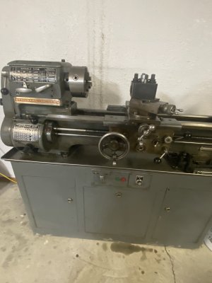
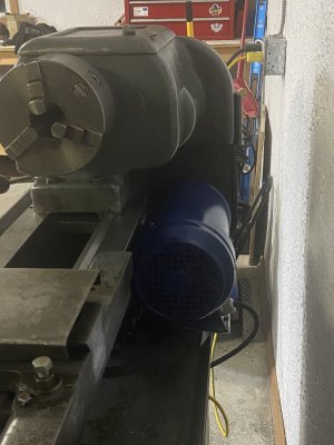
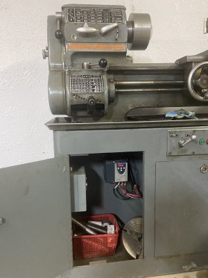
Looking forward to seeing the finished installation.I guess I’ll post pictures when I’m done, but the mechanical install of the new motor is complete.
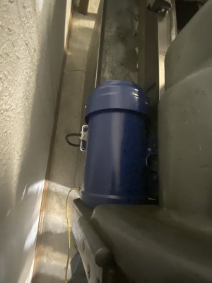
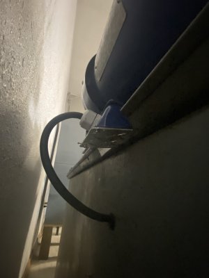
The new motor is much longer and the junction box is on the side of the motor, whereas the old motor had it on the end. The junction box on the side wasn’t working at all. I had to make a new cover for the box so it would sit flat and give clearance, and grind out part of the lip of the chip tray to get it to fit, but it’s in. And it’s staying in.
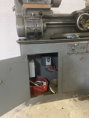
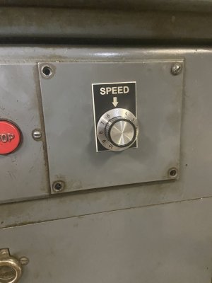
I did get the switch box to my satisfaction, utilizing the drum switch as my forward reverse, and the stop start for the contactor to still turn on the main power to the VFD. I also managed to install the potentiometer in a professional looking manner….
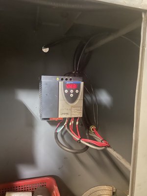
Now to mount the drive inside tomorrow and commission, and it will be done!
One of my favourite Mr. Pete moments is when he says (paraphrasing) "Could I have bought this part for $20 at the store? Absolutely! But I made it myself - with $10,000 worth of tools."Could I have bought a new one cheaper then my 2 hours working on it? Yes. Could I have learned as much or been as proud at the end result? No way!
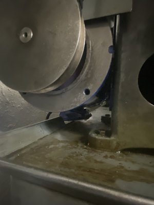
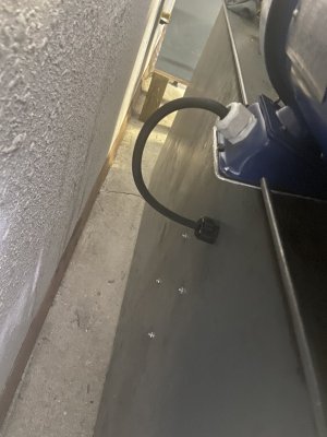
this is a pic of the back of the protection I made for the lathe.
Thanks for that Brent. A backsplash is on my project list. What gauge metal did you use?
Thanks for that Brent. A backsplash is on my project list. What gauge metal did you use?
Thanks @Brent H, with my new 3 in 1 machine this project has moved up the list@David_R8 the “splash” is 18 gauge stainless steel but 20 would be super fine to use with support. The heavier gauge is nicer to weld. The stainless was from a hospital cabinet job - I have also cut the fronts off old dishwashers for the stainless")
")