• Spring 2024 meetup in Calgary - tentative date Saturday, April 20/2024. Other regions are also discussing meet ups. If you want one in your area get going on organizing it! discussion
  • We are having email/registration problems again. Diagnosis is underway. New users sorry if you are having trouble getting registered. We are exploring different options to get registered. Contact the forum via another member or on facebook if you're stuck. Update -> we think it is fixed. Let us know if not.
  • Spring meet up in Ontario, April 6/2024. NEW LOCATION See Post #31 Discussion NEW LOCATION

Anyone tried the Accusize 5C collet chuck?

Susquatch

Ultra Member
Administrator
Moderator
Premium Member
Here is a Youtube video of that procedure by Mr. Crispin, he's a machinist working for Rolls Royce:

You guys are testing my patience. Holy crap I hate you tube. But I watched it.

To my eye, he isn't traversing the full rear face with the grinder, just the inside portion. I must be imagining that.

I also wonder why he paid zero attention to the front nose face. On my lathe that face is just like the rear face making contact after a thou or so of tightening. Recall that this face is where that teeny tiny chip was that I mentioned earlier. Is this face not important too? Or does it just go along for the ride?
 

thestelster

Ultra Member
Premium Member
You guys are testing my patience. Holy crap I hate you tube. But I watched it.

To my eye, he isn't traversing the full rear face with the grinder, just the inside portion. I must be imagining that.

I also wonder why he paid zero attention to the front nose face. On my lathe that face is just like the rear face making contact after a thou or so of tightening. Recall that this face is where that teeny tiny chip was that I mentioned earlier. Is this face not important too? Or does it just go along for the ride?
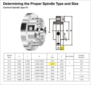
The front face of the D1-xx spindle nose is not a bearing surface.
 

Susquatch

Ultra Member
Administrator
Moderator
Premium Member
The front face of the D1-xx spindle nose is not a bearing surface.

All these years, and I didn't know that!

So prolly, that tiny chip did no harm!

Thank you!

Might make a torque adapter today. Seems like a good project for a few days before Christmas!
 

thestelster

Ultra Member
Premium Member
All these years, and I didn't know that!

So prolly, that tiny chip did no harm!

Thank you!

Might make a torque adapter today. Seems like a good project for a few days before Christmas!
But do you know what torque value is required? I don't. I guess it doesn't really matter that much, as long as they're all even.

I also tighten mine in a wheel bolt pattern. 1-4-2-5-3-6. Twice.

Also the torque requirements for tightening your 3 or 4 jaw chucks are? I have it listed in the owners manual that came with my 3-jaw.
 

Dabbler

ersatz engineer
The front face of the D1-xx spindle nose is not a bearing surface.
What @RobinHood aluded to and what I have heard is quite different. For me it is not a hill to die on. But here goes: when correctly positioned, the backplate must make intimate contact with the D1-x face., From what I understand, this prevents chuck tilt, and resists axial forces incurred when making large diameter cuts. On my D1-6 Pratt Bernard chucks, there is full contact on my LeBlond lathe, for instance.
I also tighten mine in a wheel bolt pattern. 1-4-2-5-3-6. Twice.
Exactly how I was taught too!

--one last tidbit... Any D1-x chuck must be 'stuck' when releasing the cams, and needs a sharp wrap from a soft hammer to release. Several used lathes I have examined, the owner stoned the taper so it would 'fit right' and the chuck could fall off by itself. Needless to say I ran away from those disfigured lathes.
 

Susquatch

Ultra Member
Administrator
Moderator
Premium Member
Before doing anything, I took the time to measure my spindle runout. The shop is not warmed up yet but approximately 1 micron on the taper and 1.5 or so on the flat at the outside surface using my Mahr millimess 1 micron test indicator. My cam lock holes intersect the inside relief so I could not take a reliable measurement there. I don't think I'll be touching it.

I then mounted my Bison 5C Collet Chuck and measured its taper runout at about 1 micron. At first I thought that can't be right so I applied a tiny force on the Noga holder and sure enough, very smooth and predictable movement so it isn't sticking. A good example of how I set it up to index on the lowest runout. Still holding great about 9 years after I bought the chuck.

Next I installed a hardinge 1/4" collet with one of my better endmills. Same runout at the base of the endmill but a bit over 3 out near the flutes 1 inch away. Perhaps that would get better with deeper engagement in the collet but then I wouldn't be able to measure at that length. I have no precision rods I would trust for this test. They are on my Kijiji/marketplace search list.

I confess that I can't get the indicator into position for a 90 degree measurement so the results might be very slightly worse. But given the very small measurement, I doubt I could see the difference.

Those results are all turning the spindle by hand using the rear spider.

Of course, the acid test is the concentricity and consistency across length of the parts I turn on it.

All in all, a whole lot better than I remembered. Another reason I love my collet chuck.
 

Susquatch

Ultra Member
Administrator
Moderator
Premium Member
But do you know what torque value is required? I don't. I guess it doesn't really matter that much, as long as they're all even.

Actually, no I don't. I've always assumed the small t-handle was deliberately sized to prevent overtorquing the cam bolts. Being a big fellow, I've always been gentle with them.

I have not assessed the info @PeterT has provided above yet. This will help me decide what size of torque limiter to acquire.
I also tighten mine in a wheel bolt pattern. 1-4-2-5-3-6. Twice.

I do the same thing but 3x instead. Once to just get them started, again to get them up to 50% or so, and then again to tighten them up.
Also the torque requirements for tightening your 3 or 4 jaw chucks are? I have it listed in the owners manual that came with my 3-jaw.

Oh oh....... I didn't know they are different! I'm not immediately able to see why that would be. If the base of the chuck is at least as big as the base of the spindle, shouldn't they all be the same?
 

TorontoBuilder

Ultra Member
Here is a Youtube video of that procedure by Mr. Crispin, he's a machinist working for Rolls Royce:


I watched this series from when he started posting it about a month ago... very informative stuff. In the series on grinding theory he specifically tackles alignment with the spindle on two planes. Between these and a few other videos on grinding I think I'm ready to tackle regrinding my spindle nose taper and face if necessary
 

PeterT

Ultra Member
Premium Member
The shop is not warmed up yet but approximately 1 micron on the taper and 1.5 or so on the flat at the outside surface using my Mahr millimess
All in all, a whole lot better than I remembered. Another reason I love my collet chuck.

Bison references their 5C chucks TIR at 0.0004". I think a Hardinge precision collet is 0.0002". End mill shanks, I dunno, maybe 0.0002-0.0005"? So you have 3 potentially cumulative tolerance variation sources downstream of the spindle & you get the same runout of 1 micron (0.000039") at the base of the EM? The chuck is rated 10X more runout than your headstock assembly. You should be thanking the Gods of Probability, or the Asian lathe builders LOL.
 
Last edited:

Susquatch

Ultra Member
Administrator
Moderator
Premium Member
You should be thanking the Gods of Probability, or the Asian lathe builders LOL.

I certainly agree! You should have seen my face when I saw the numbers. Needle wasn't moving. Had my milliness gone south? Did I adjust it wrong? Was something binding?

Nope nope nope. I even reached over and pushed manually on the nose to see if the needle would move. Yup, it did! So nothing obvious wrong. Can't wait to turn and test a part per @Dabblers suggestion. Not touching anything till then!
 
Interesting that you all forget one simple thing on your mounts. If the lathe mount is worn or damaged, turn it or grind it to spec. No matter what happens it will be true to your machine in that set up.

Scared of turning or grinding, don't be as you are likely only taking of 1/10's of Thousands (maybe up to 0.001) just to clean things up. If you are taking 0.005 you have serious issues that need to be address on your machine and the mount is likely the least of your issues.

Finally, precision and some of the values being chased are not within the realm that most can achieve with the equipment and tooling that we have. This is one of those pet peaves that that gets me upset.

On for those with OCD that work to those levels (and some have posted their projects and work) hats off, you truly understand that you precision is the craftsmanship of your work and skill to get it there and not that of the machine and don;t waste you time chasing something on the mahine that is beyond its limits, but instead work around it to achieve the results.
 

Susquatch

Ultra Member
Administrator
Moderator
Premium Member
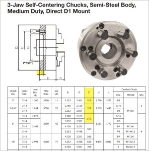
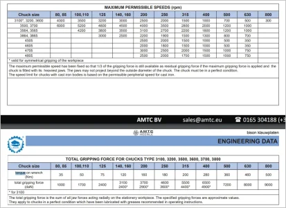
I've heard that the tommy bar T-handle chuck key design is partially intended to limit excessive Gronk torque. The chuck specs seem to support that.

It's not easy to get the really important stuff done this time if year. Too many honey do's.

I can't really make heads or tails of this info Peter. I think these charts are all referring to the torque on the collet tightening mechanism - not the CamLock Studs. The other chart you copied from GTS is similarly suspect.

On a related topic, I looked at the bison catalog you linked to and could not find all the different d1-x mount choices for collet chucks. Have they dropped those?
 
Top