But before you decry that a lathe chuck is unacceptable, whether it's a 3-jaw, 4-jaw, or collet, you better measure your spindle nose first.
Below is what Accusize requires for you to achieve their stated TIR. (those numbers are metric. The equivalent conversion is 0.00016" & 0.0002")
And Bison wants 0.0001" accuracy on those surfaces.

And, though you might say, well, I'll get a Set-Tru, or Adjust Tru, or just use a 4-jaw and indicate it in. And yes, that will work, but only at that spot where you are indicating. If there is any run out at your spindle nose, no matter what you do, you will have run out further out on your work piece.
But does it really matter? It depends. If you are machining a part on the lathe, and you do all the work while it is in the chuck, it will come out perfectly fine.
But if you have to take that part out, and then you determine you forgot to machine feature on it, and then you go to re-chuck it, it will not run true for the whole length of the part, even if you re-adjust the set screws, it would only have zero run-out at that spot you are indicating.
So before you decide on anything, measure your spindle nose, and then determine whether a Set-True feature is useful.
Below is what Accusize requires for you to achieve their stated TIR. (those numbers are metric. The equivalent conversion is 0.00016" & 0.0002")
And Bison wants 0.0001" accuracy on those surfaces.
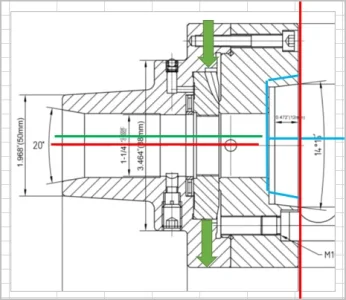
The method of measuring 0269-5C Collet Chucks
1. CHECK THE RUNOUT OF THE LATHE SPINDLE FIRST. ADJUST THE RUNOUT VALUE OF THE NOSE WITHIN 0.004MM; OF CYLINDER OR TAPER WITHIN 0.004MM SHOWN BELOW.
And, though you might say, well, I'll get a Set-Tru, or Adjust Tru, or just use a 4-jaw and indicate it in. And yes, that will work, but only at that spot where you are indicating. If there is any run out at your spindle nose, no matter what you do, you will have run out further out on your work piece.
But does it really matter? It depends. If you are machining a part on the lathe, and you do all the work while it is in the chuck, it will come out perfectly fine.
But if you have to take that part out, and then you determine you forgot to machine feature on it, and then you go to re-chuck it, it will not run true for the whole length of the part, even if you re-adjust the set screws, it would only have zero run-out at that spot you are indicating.
So before you decide on anything, measure your spindle nose, and then determine whether a Set-True feature is useful.