• Scam Alert. Members are reminded to NOT send money to buy anything. Don't buy things remote and have it shipped - go get it yourself, pay in person, and take your equipment with you. Scammers have burned people on this forum. Urgency, secrecy, excuses, selling for friend, newish members, FUD, are RED FLAGS. A video conference call is not adequate assurance. Face to face interactions are required. Please report suspicions to the forum admins. Stay Safe - anyone can get scammed.
  • The 2026 Calgary Area Meetup is set for Saturday May 30th at 10am. The signup thread is here! Robinhood has graciously offered to host the meetup again this year. Please note that you MUST RSVP to the notice linked above if you wish to come.

3D Printer Happened

To answer another question about backflip.ai, I personally have not used it myself. I do work in software, and use AI on a day to day basis. The fact that they use a foundation model gives me hope that it is good at what it claims. Probably worth throwing $20 at it with a few projects in mind. I would think converting 3d scans to CAD is the ultimate use case for this.

I agree, AI seems to be taking these kinds of applications in a positive direction. My guess is not slam dunk but even if it does some of the heavy lifting processing in a reasonable manner, might be worth it. Fom what little I've lurked around 3D scan projects, it seems to be one of those -great now I have a point cloud, now the real work starts. If its 'just' a shape like a garden gnome, nobody will see the differnce. If its a mechanical thing with specific dimensions, the operator has to oversee & edit those issues. So if auto pilot get 90% correct & designer is left to alter 10% thats a win. But if designer ends up doing 70% of the work to fix or fudge autopilot output, the needle swings the other way.

Loose comparison. I've been checking out different photo apps. Its another industry with AI being name dropped like crazy. In some cases its just gimicky, but in other cases like so called simple masking, its amazing what AI figured out compared to the hours spent by a human. A couple of brush strokes to tell AI this is the subject or this is the background & away it goes. Zoom in at the pixel level & its masking incredibly fine detail. And then it just goes from there. And with that comes the processing specs. Processor/ram/GC... need to be quite robust to handle the crunching.
 
Been a while since I printed anything. Too many nasty wrinkles in my life.

I've had this really nice camera tripod for a few decades. I don't remember where I got it. But I do know that's it's been pretty much useless because I don't have a quick adapter for it. They don't sell them anymore - been MIA for decades.

I had a need for the tripod today so I decided to mill an adapter from aluminium. I was taking measurements when I had this idea to look on printables and other 3D model websites.

Sure enough there were several. So I picked the one I liked best and tried to print it. No good. This particular model doesn't print directly. I had to slice it first using the desktop program. No biggie, I did that and told it to go.

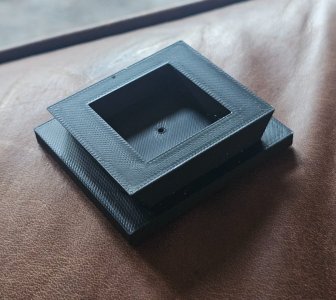
15 minutes later I had an adapter in my hands. But..... It was too loose on both X and Y. Back to the slicer and stretch x & y by 3.5% based on measurements of the shoe and the printed adapter. Ya, not yet buddy. Now it's too tight. Actually, it could be forced, but easy peasy to print again at 3%. Plugged it in and pressed go.

Fits perfect.

20260927_172644.jpg

Just need to add a 1/4-20 thumbscrew and drill for it.

Nice! Very happy!

Heck, might even take a few thou off the tight adapter on the mill. Why not? It's a trivial operation.
 
Just need to add a 1/4-20 thumbscrew and drill for it.
Heck, might even take a few thou off the tight adapter on the mill. Why not? It's a trivial operation.

...and so it begins... 😉
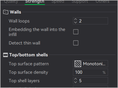
Just remember when you take a skiff off here & there post-print for one reason or another, you have to pay attention (typically increase) wall loops & shell layers in the slicer. Lest there be nothing left but infill after the skiff.
1790548808913.png
 
Been a while since I printed anything. Too many nasty wrinkles in my life.

I've had this really nice camera tripod for a few decades. I don't remember where I got it. But I do know that's it's been pretty much useless because I don't have a quick adapter for it. They don't sell them anymore - been MIA for decades.

I had a need for the tripod today so I decided to mill an adapter from aluminium. I was taking measurements when I had this idea to look on printables and other 3D model websites.

Sure enough there were several. So I picked the one I liked best and tried to print it. No good. This particular model doesn't print directly. I had to slice it first using the desktop program. No biggie, I did that and told it to go.

15 minutes later I had an adapter in my hands. But..... It was too loose on both X and Y. Back to the slicer and stretch x & y by 3.5% based on measurements of the shoe and the printed adapter. Ya, not yet buddy. Now it's too tight. Actually, it could be forced, but easy peasy to print again at 3%. Plugged it in and pressed go.

Fits perfect.

View attachment 87438

Just need to add a 1/4-20 thumbscrew and drill for it.

Nice! Very happy!

Heck, might even take a few thou off the tight adapter on the mill. Why not? It's a trivial operation.
Now that you have this nice model you can measure it and mill one out of aluminum
 
Been a while since I printed anything. Too many nasty wrinkles in my life.

I've had this really nice camera tripod for a few decades. I don't remember where I got it. But I do know that's it's been pretty much useless because I don't have a quick adapter for it. They don't sell them anymore - been MIA for decades.

I had a need for the tripod today so I decided to mill an adapter from aluminium. I was taking measurements when I had this idea to look on printables and other 3D model websites.

Sure enough there were several. So I picked the one I liked best and tried to print it. No good. This particular model doesn't print directly. I had to slice it first using the desktop program. No biggie, I did that and told it to go.

15 minutes later I had an adapter in my hands. But..... It was too loose on both X and Y. Back to the slicer and stretch x & y by 3.5% based on measurements of the shoe and the printed adapter. Ya, not yet buddy. Now it's too tight. Actually, it could be forced, but easy peasy to print again at 3%. Plugged it in and pressed go.

Fits perfect.

View attachment 87438

Just need to add a 1/4-20 thumbscrew and drill for it.

Nice! Very happy!

Heck, might even take a few thou off the tight adapter on the mill. Why not? It's a trivial operation.
Well, well. Finally I see a post after this investment. I have been watching and waiting in effort to understand all of this and how it can be of benefit to me. Keep posting, keep dreaming, keep creating. I want to learn more, to me, you are the teacher.

Well done.


TonyK.

Grimsby Ontario Canada.
 
Lest there be nothing left but infill after the skiff.

So I gather I should have added that stuff in anticipation of needing to cut a little off in future.......

A little too late for that. I just did a normal print. But it's a good warning - at least I know now to split what I do remove between both sides to reduce the risk.

Even if I fail, nothing really to lose except a little filament.
 
Just remember when you take a skiff off here & there post-print for one reason or another, you have to pay attention (typically increase) wall loops & shell layers in the slicer.

Milled enough from each side to fit. No sign of soft infill or internal spaces.

I call this a total success. Learned something too. I guess I should say I now know about an issue I didn't know about before. I didn't really learn anything yet.....

What is a loop?

What is a wall?

What is a shell layer?

What is %infill?
 
Only because you're a 3DP newby and you didnt watch the YouTube video I recommended, I'll use my AI superpowers. Just this once.


In Bambu Studio (and modern FDM 3D slicing software in general), these four terms describe how your 3D model is translated into physical plastic paths.
Here is what each term means and how it functions inside the slicer:

What is a Loop?​

A loop (often referred to as a perimeter or contour) is a single, continuous closed path traced by the print head to draw the outline of a slice layer.

  • How it works: A single wall thickness is built out of one or more concentric loops running side-by-side.
  • In Bambu Studio: You will see loops differentiated as Outer Wall (the outermost loop exposed to the surface) and Inner Walls (the loop or loops printed behind the outer wall to build up strength).

What is a Wall?​

A wall is the complete vertical shell structure formed by stacking loops on top of each other across successive layers to bound the sides of your model.

  • How it works: In Bambu Studio, you set this via Wall Loops under the Quality/Strength tab. Setting "Wall Loops: 3" tells the slicer to print 3 parallel loops (perimeters) on every layer to form the side boundaries of the print.
  • Function: Walls provide structural rigidity, control mechanical strength against side loads, and dictate the external surface quality and dimensional accuracy of the part.

What is a Shell Layer?​

A shell layer refers to any solid layer of plastic that seals the exterior envelope of the 3D print—specifically the horizontal top and bottom boundaries.

  • Top & Bottom Shells: In Bambu Studio, these are configured under the Strength settings as Top Shell Layers and Bottom Shell Layers.
  • How it works: While walls seal the vertical sides, top and bottom shell layers print as 100% solid, fully-filled horizontal surfaces to completely enclose the internal hollow/infill region. For example, setting 4 top shell layers ensures the slicer prints 4 completely solid layers over the sparse infill before finishing the top of the model.

What is % Infill?​

% Infill (or Infill Density) is the percentage of internal volume within the model's outer shell that is filled with plastic.

  • How it works: Because 3D prints are rarely printed 100% solid, the slicer generates a geometric pattern (e.g., Gyroid, Grid, Honeycomb) inside the hollow interior created by the walls and shell layers.
  • Standard Ranges:
    • 0% Infill: Completely hollow inside (supported only by walls and top/bottom shells).
    • 15% – 20% Infill: The standard range for general-purpose visual and light-use prints (balances strength, print time, and material use).
    • 40% – 100% Infill: Used for high-stress mechanical parts, functional brackets, or thread engagement areas where maximum impact resistance or stiffness is required.
 
If your part needs to be stronger, don't instantly go to adding more infill. Add more walls and shell layers. This has been proven to make parts much stronger then just adding infill. A middle ground approach is likely the best option. It has to do with how the infill is anchored to the walls. Printing to 100% of either will most likely give you massive elephants foot.
 
The number of perimeters or perimeter layers is the simplest and biggest control lever for part strength. 2 perimeter layers is default. 3 or 4 is significantly stronger. For parts that have a lot of stress then I often tell it to print 12 perimeters or more.

https://www.printables.com/model/169479-roloc-compatible-35mm-arbor-2-ish
Like this roloc adapter - I print it with many perimeters - 20? - so it is a strong as possible. with fewer perimeters it just breaks.


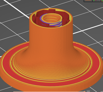
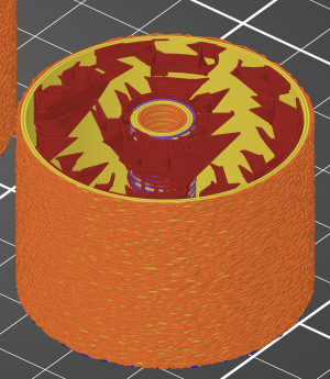
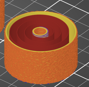
Here is the inside of the roloc adapter with 2 perimeters - you can see the infill but the part is mostly hollow. There are 2 perimeters on the outside and 2 on the threaded ID (plus a couple more for the thread form).
1790738453779.png


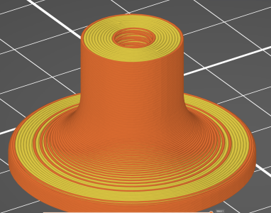
And here is the adapter with 12 perimeters - you can see it's much denser.
1790738544920.png
 
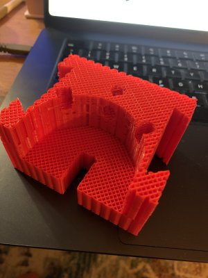
This is interesting - this part is printed without walls, no top and no bottom layer, or more simply with zero perimeters. Just the fairly dense infill is printed.

Ooouuu! That looks like something I'd like to print! Is it BXA by any chance? Love that it's reversible. Can you share the file John?

And yes, the print without walls is interesting indeed! Learning sooooo much!

Another thing I ran across on my printer is the variety of infill patterns. I wonder how they all affect strength? If not that, then why the choices?
 
You're in the most fun stage of the whole thing .... constant new ideas and applications. What a hoot, right? 🙂

Sometimes yes, sometimes no.

Right after that print, high on adrenaline and confidence, I tried to print a 9 hour job of dessicant boxes for my AMS. 17 parts altogether. Other than the front left corner part that made a gooey mess on the inside corner of the part, it printed fine. All the lids fit and the breather holes didn't leak dessicant.

BUT,,,,, Nothing fit my printer. NOTHING! Wrong kit? Did it remember my scaling for my quick mount? WTF!!! 9 hours wasted!
 
Ooouuu! That looks like something I'd like to print! Is it BXA by any chance? Love that it's reversible. Can you share the file John?

And yes, the print without walls is interesting indeed! Learning sooooo much!

Another thing I ran across on my printer is the variety of infill patterns. I wonder how they all affect strength? If not that, then why the choices?
ah yes but of course!
the BXA indicator holder: https://www.printables.com/model/297110-lathe-compound-taper-angle-setting-tool
Chaychuck conceived of this BTW.

the roloc adapter from above: https://www.printables.com/model/169479-roloc-compatible-35mm-arbor-2-ish

The different patterns are weaker/stronger and of course slower/faster to print. Some are water proof, others are I think mostly just interesting. I've been using the lightning pattern to speed up print times. Below. You can see there is no infill towards the bottom and the infill grows from the sides to support the top layer. I also turned on the fuzzy skin feature you can see on the outside of the part.

1790784887085.png

here is Archimedian Chord, or spiral. If you turned off the top and bottom layers then it could be a circular spring.

1790784996904.png
 
Last edited:
Back
Top