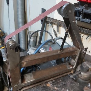
So, to get the discussion going, here is what I am starting with. ....the pulley (more like a flywheel) on the motor is about 5 3/4" in diameter and about 1" wide. The grooves you see are for a micro v belt. So, to me, the wheel is too narrow to be a direct drive pulley, and I would like a larger diameter to increase surface feet per minute. Most knife makers ( correlating to efficency) seems to be about 5000 sfpm. I would like to keep the RPM in a reasonable range, although not sure what that is yet for these motors. Having said that, I have not tested the motor to see what it actually like to run at. But I had a 7 inch diameter in mind ..about 2700 RPM. I would start with anything from the existing diameter to a custom made 7 incher (when stock avails itself to me. )
The thread holding the flywheel on is a 1/2" left hand so easy enough to make a whole new drive pulley. Casting one? Making one out of pipe and plate? Modifying the flywheel? I have seen plans for shop built stuff before using MDF as the pulley. On a machinist's forum, this would be frowned upon but practically speaking, to bond a piece or two of MDF to the existing fly wheel to have a 2" wide drive pulley,with the cast iron flywheel as the base ...... might actually work....

Mounting the motor...I don't like the existing mounting brackey but would reuse the holes in the motor chassis.
I would put a tach on it but one that displays SFPM instead of RPM. Couple ways to do this, Microcontroller (Arduino) to do the math and display it or a pulley sized so that the RPM reflects the SFPM ie if the circumference of the sensing pulley is ten inches, then SFPM is 10 times the tach display or add magnets as multipliers.
I have 4 scrapped treadmills and 3 complete controllers/motors. One motor where the controller was pooched. So saying, if you want to do this and have not looked into Treadmills as resources, it might interest you.
Cheers,
Shawn

