YASMT: Allen Bradley Mag switch wiring for Single Phase

RobinHood

Ultra Member
Premium Member
Congrats! Well done.

I took a video, but the forum wont let me upload it. Lol.
You can use a program called “Streamable.com”. You upload the video onto their platform and then they give you a link which you can post here. The basic version is free.
 
Congrats! Well done.


You can use a program called “Streamable.com”. You upload the video onto their platform and then they give you a link which you can post here. The basic version is free.

Fyi, you may note that I have the lead screw, saddle and apron removed. No need to panic. ;) Cleaning and inspection.

One last note. I didnt run a ground wire all the way to the motor from the junction box where the incoming line comes in. The incoming line is grounded to the juntion box which is metal and is bolted to the base. This is the way the 3ph motor was configured. Thoughts? Any risks here? My woodworking 220v stuff always has a ground run to the motor via a bond at the mag switch.
 
Last edited:

PeterT

Ultra Member
Premium Member
@calgaryguy Is it my imagination or at 0:36 when you switch in reverse, chuck is rotating in forward direction? (CCW if viewed on end from tailstock).
I couldn't make out the other starts by the time chuck was moving
 

Tecnico

(Dave)
Ok guys, no need to let the smoke out of anything…

Nobody says you need to connect the Power Side of the contactor while you are establishing the Control circuit. Two separate items, at least in my view. I only ever connect the Power Side after I am 100% sure that the control circuit works properly. That means:

a) the FWD /Neutral/REV switch is wired properly
b) the contactor Control is wired correctly
c) the door safety switch is in the circuit properly
d) the green Start switch is working properly
e) and the red Stop switch is working properly

Other than the contactor coil, none of the components need line voltage to test the circuit - a little 9V battery will work just fine ==> no smoke.

Now onto to the circuit:

Make sure the AB contactor‘s coil is rated for the voltage of your control circuit. The only sure way to know is take the contactor apart and look at the coil physically.

The grey switch with the handle is a FWD / NEUTRAL / REV switch. It needs to be wired such that in Neutral (Center) position, the control voltage to the contactor is interrupted.

The door safety switch is the “Master Switch”. If it is “open“, no matter what button(s) you press, the lathe must not start.

The green Start button is the only control that makes the contactor coil close - after the direction of rotation of the spindle has been preselected by the FWD/N/REV switch. The red Stop switch is the normal way of turning the lathe off. If you were to use the F/N/R switch while the lathe is running, the contactor will open and the motor stop.

The whole thing needs to be wired such that, after a line power failure, the contactor opens and stays open until the operator decides that they want to run the lathe again after the line power comes back on.

The circuit needs to be set-up such that it latches the contactor after the green momentary Start button has been depressed - but only with the door safety switch closed AND a direction of rotation preselected.

When I had the 9” Utilathe, that’s how it was set up. I believe there are wiring diagrams available online for the Rotary switch that is installed in your lathe.

Here is the wiring diagram for the SM1120. It has the exact same controls (minus the door safety switch) as your 9“ Utilathe. It shows 3 phase motor(s), but that does not matter. Just use two (L1 & L3) of the lugs of the contactor instead of three. Make sure the “heaters” can handle the current of your single phase motor. Get properly rated ones once you have the circuit established and are ready to connect the load. Wire the door safety switch in series as the first item in your control circuit. Test everything with low voltage DC.

View attachment 21977

Gents

I was about to start a new thread on adapting the wiring of the contactor of my 3 phase (220V, 3/4 HP) SM 1120 to run the 1 phase (110/220) 1 HP motor that came with it but there's so much good background here that it's worth having it all in the same place. I have to say I was pleasantly surprised to find this thread here at home on CHMW!

@RobinHood , I have a question about what you said:
Just use two (L1 & L3) of the lugs of the contactor instead of three.

By doing this you bypass the two normally closed switches in the line between L2 and the coil. See diagram above. These appear to be the thermal switches of the two "heaters" and removing power from the L2 line would appear to disable the magnetic coil.

I have read in other resources a suggestion to connect L1 & L3 as you said but take the output from T3 and connect it to L2 (thus powering the coil) and connecting the output of T2 to to contact 1) of the drum switch.
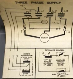
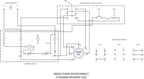
I like this approach because it is the least invasive mod to the existing wiring. Does this make sense or am I missing something here?

Good advice on doing testing without connecting mains power, I'm not a big fan of letting magic smoke escape!

@calgaryguy , thanks for posting the link to the heater data sheet.

D :cool:
 

RobinHood

Ultra Member
Premium Member
By doing this you bypass the two normally closed switches in the line between L2 and the coil.

That is correct.

That is why AB tells us to connect “X2 to L3“ to power the coil.

D4F0E0B1-6CBB-4891-83D0-52409D059E08.png

Now the coil is powered again; plus the latching coil circuit is protected by the motor thermal switches and is de-energized should the motor overheat and thus open the contacts.

but take the output from T3 and connect it to L2 (thus powering the coil) and connecting the output of T2 to to contact 1) of the drum switch.

I don’t think your “START” button will work in that case as the T3 leg is only powered after the contactor at L3 is closed. The L2 side of the coil needs continuous power for it to energize / stay energized. The AUX contacts at 2-3 perform the latching of the coil circuit to keep all three main contacts closed.

A77F0C62-4262-41E9-899A-FD90CCE249DA.png

IIRC, the drum switch on the SM1120 is not supposed to “start the lathe”. It is there to select FWD or REV only and to make sure the contactor opens (thus shuts down the lathe) when the operator switches spindle direction without first stopping the lathe with the “STOP” button.

EDIT: just came back from the shop; the drum switch is wired just like I describe above.
 
Last edited:

Tecnico

(Dave)
@RobinHood Thanks!

I’ll have to have a closer look for the X2 line, maybe pull the box out so I can get a better look at the connections. Right now, peering in on hands & knees isn’t doing it for me.

Right now the box isn’t connect to anything so it won’t be difficult to pull it out.

D :cool:
 

Tecnico

(Dave)
OK, I'm back!

I found some time yesterday to have a good look at the wiring and ring it out vs. the SM wiring diagram and I was pleased and even a bit surprised to find that it hadn't been modified over the years. WIN!

A little contact cleaner on the drum & other switches and everything appears happy and ready to convert to single phase.

I also identified the X2 line (not marked....). I will note that AB gave instructions on how to config. the mag switch for 1 phase but didn't mention the motor so a bit more homework was needed.

After sitting down with the SM wiring diagram and the motor connect data (Baldor) I came up with this connection plan:

SM1120 Wiring Diagram - 1 Phase.jpg

The proof is in the pudding, it runs! Both directions! No magic smoke released either. :D

I honestly don't know if all motors are configured/labelled like my Baldor but it would appear to be the same hookup as @calgaryguy found for his and as @Brent H showed on his diagram. I also lucked in with the "heaters" because my machine was already configured to run on 220V so no searching for different heating elements needed.

Next up is to crack open the motor and see what the telltale (scraping?) noise was when it wound down. Probably protesting about sitting around on the shelf too long.

Thanks gents, appreciate the advice. :)

D :cool:
 
make sure your 'motor starter heaters' in the AB switch are the right spec for your motor/phase. Thats something I had to change up.
 

Bandit

Super User
Tecnico, if the motor has a fan with a shield around/over it, check that first for making the "noise" when slowing down. Also take a good look around the drive end of the motor and driven shaft/ pulley( belt drive). It save a lot of work (or add some). A chip, etc. maybe rubbing, dragging at various rpms causing noise. Sometimes things move when slowing or speeding up.
Hope fully not a bearing!
 

Tecnico

(Dave)
make sure your 'motor starter heaters' in the AB switch are the right spec for your motor/phase. Thats something I had to change up.

Good point, I skipped over that one a bit quickly reconfiguring the wiring. I won't be using the machine for a while yet, at least the existing ones would give a very conservative safety factor!

Now, for the heaters and just to throw it out there for feedback, I have:

- A one HP motor/max 7.4A
- Bulletin 709, Size 00 magnetic switch
- Two relays (not open block type)

This points to Table 13, full loads less than 7.63A so it's looking like I need a N28 heater element.

For ref: AB Bulletin 815

Make sense?

Tks.

D :cool:
 

Tecnico

(Dave)
Tecnico, if the motor has a fan with a shield around/over it, check that first for making the "noise" when slowing down. Also take a good look around the drive end of the motor and driven shaft/ pulley( belt drive). It save a lot of work (or add some). A chip, etc. maybe rubbing, dragging at various rpms causing noise. Sometimes things move when slowing or speeding up.
Hope fully not a bearing!

@Bandit the motor has an integral impeller/fan in the case so perhaps a bit different from what you're thinking. For sure it's not a TEFC. I don't think there are any chips in it either because it's not the (3 phase) motor that came off of the lathe but who knows what else might be in there from it laying around, LOL!

I suspect it might be bearings with old, dried up grease in them but I'm not too fussed about it, it's about what I'd expect after it laying around for years. It's the motor that the previous owner planned on putting on it 30 years ago. As long as it runs now, I can go from there! :)

D :cool:
 

Tecnico

(Dave)
Just to close the loop on this, I ordered a pack of two N28 heaters from Industrial Automation in Hamilton for $10.61 total. I also talked to Graybar and they offered me the same for $69.00!

D :cool:
 
Top