YASMT: Allen Bradley Mag switch wiring for Single Phase

"Yet Another Standard Modern (9") Thread"

My former-SAIT Standard-Modern 9" Utilathe came with a 3ph 1/3hp 1725rpm motor. I've replaced it with a 3/4hp Baldor single phase 1800rpm motor.

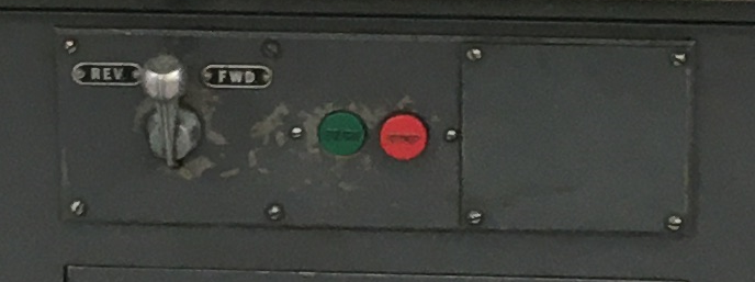
The SM base has a control panel with on/off buttons and a fwd-rev switch

1647223087005.png


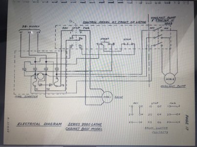
All good, @YYCHM provided a wiring diagram from the manual showing how to wire the front control panel for 220v 1ph.

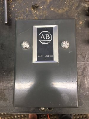
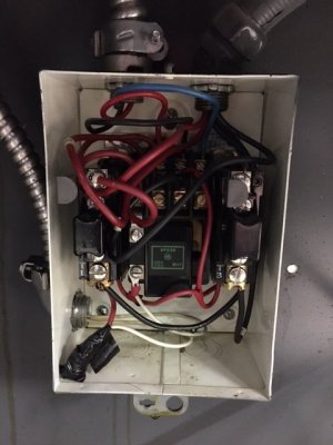
My challenge now is wiring the Allen Bradley Mag switch located inside the cabinet

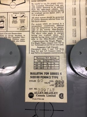
IMG_2342.JPG IMG_2343.JPG

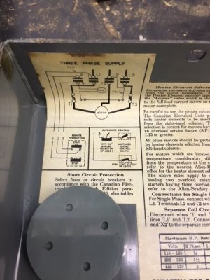
IMG_2344.JPG IMG_2345.JPG

I've googled for "allen bradley 709 taf" with no luck. Is there anyone out there familiar with these mag switches or knows of a internet resource with AB manuals? I know modern mag switches are usually 1ph and 3ph capable depending on how they are wired. Are these older AB mag switches the same?
 
Last edited:
I may have already answered my own question by reading the 'Connections for Single Phase' in the pic 1st row, right. RTFM. Lol.

I have 2-3 of these AB mag switches around, but the lack of a more complete manual makes me nervous to use them. I dont like letting 'magic smoke' out of electrical bits.
 
Last edited:

YYCHM

(Craig)
Premium Member
LOL.... One peek in that box and I'd be off to PA to buy a drum switch:p

That and a big a.s paddled ESD switch to hang on the front of the stand.
 
Last edited:
All good. I should be able to 'figure' it from the writing on the inside of teh cover.

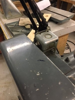
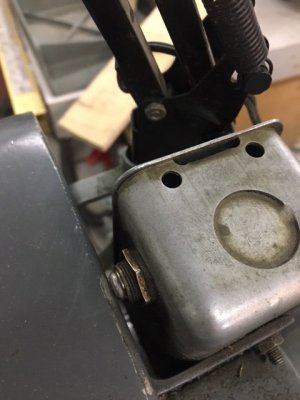
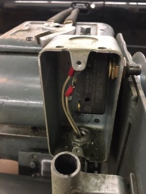
The wiring is alot more complex than usual as there is a remote on/off, a reverser, AND a power disconnect switch that SAIT seemed to have added at the belt housing cover. I'll post a pic when I get a chance - suffice to say its a button switch that the belt housing cover pushes against to allow power to flow. When teh cover is open the button goes to a 'closed' state.

EDIT:
IMG_2346.JPG IMG_2347.JPG IMG_2349.JPG IMG_2350.JPG
 
Last edited:

YYCHM

(Craig)
Premium Member
All good. I should be able to 'figure' it from the writing on the inside of teh cover.

The wiring is alot more complex than usual as there is a remote on/off, a reverser, AND a power disconnect switch that SAIT seemed to have added at the belt housing cover. I'll post a pic when I get a chance - suffice to say its a button switch that the belt housing cover pushes against to allow power to flow. When teh cover is open the button goes to a 'closed' state.

Seriously????
 

YotaBota

Mike
Premium Member
Instructions???????? We're men,,,,,,, we don't need no stinkin instructions!!!!!LOL
I was rescued by the VFD, wired the drum switch to the VFD and used the red/green buttons to control the contactor feeding the VFD.
 
Instructions???????? We're men,,,,,,, we don't need no stinkin instructions!!!!!LOL
Having let the 'magic smoke' out of a few electrical devices in my life I'd rather be cautious. Especially with a brand new, never run, Baldor motor and a 220v 30A circuit. Lol
 

YotaBota

Mike
Premium Member
The SM1120, the story is in my cleanup and rewire thread.
 

YYCHM

(Craig)
Premium Member
I edited the post above with pics ^^^^^^^

That would be the first thing to go, if it were mine:p

Is the RWD/REV switch on the stand a honest to goodness drum switch? Wouldn't that solve the 1PH wiring problem entirely?
 
That would be the first thing to go, if it were mine:p
I kinda like the safety factor. No reason not to keep it.

Is the RWD/REV switch on the stand a honest to goodness drum switch? Wouldn't that solve the 1PH wiring problem entirely?
I dont know if it is or isnt. I think your 'drum switch' is a reverser and a on/off switch combined, not sure
.
I'm going to be running it on 220v, and I'd prefer to leave the magnetic switch in place - that way if I kick a breaker or the power goes out while I'm using the lathe theres no chance of the machine spinning back up when power is restored. This is standard on all my heavier woodworking gear.

Besides, getting it work under 220v 1ph shouldnt be an issue once I do some 'figuring' on the existing wiring. The AB mag switch is the complex part. Having the factory buttons on the front work keeps its 'originality' IMO.

EDIT: Adding a big 'oh shit' paddle safety switch in an easily slappable place like @YYCHM 's is something to consider.
 
Last edited:

RobinHood

Ultra Member
Premium Member
Ok guys, no need to let the smoke out of anything…

Nobody says you need to connect the Power Side of the contactor while you are establishing the Control circuit. Two separate items, at least in my view. I only ever connect the Power Side after I am 100% sure that the control circuit works properly. That means:

a) the FWD /Neutral/REV switch is wired properly
b) the contactor Control is wired correctly
c) the door safety switch is in the circuit properly
d) the green Start switch is working properly
e) and the red Stop switch is working properly

Other than the contactor coil, none of the components need line voltage to test the circuit - a little 9V battery will work just fine ==> no smoke.

Now onto to the circuit:

Make sure the AB contactor‘s coil is rated for the voltage of your control circuit. The only sure way to know is take the contactor apart and look at the coil physically.

The grey switch with the handle is a FWD / NEUTRAL / REV switch. It needs to be wired such that in Neutral (Center) position, the control voltage to the contactor is interrupted.

The door safety switch is the “Master Switch”. If it is “open“, no matter what button(s) you press, the lathe must not start.

The green Start button is the only control that makes the contactor coil close - after the direction of rotation of the spindle has been preselected by the FWD/N/REV switch. The red Stop switch is the normal way of turning the lathe off. If you were to use the F/N/R switch while the lathe is running, the contactor will open and the motor stop.

The whole thing needs to be wired such that, after a line power failure, the contactor opens and stays open until the operator decides that they want to run the lathe again after the line power comes back on.

The circuit needs to be set-up such that it latches the contactor after the green momentary Start button has been depressed - but only with the door safety switch closed AND a direction of rotation preselected.

When I had the 9” Utilathe, that’s how it was set up. I believe there are wiring diagrams available online for the Rotary switch that is installed in your lathe.

Here is the wiring diagram for the SM1120. It has the exact same controls (minus the door safety switch) as your 9“ Utilathe. It shows 3 phase motor(s), but that does not matter. Just use two (L1 & L3) of the lugs of the contactor instead of three. Make sure the “heaters” can handle the current of your single phase motor. Get properly rated ones once you have the circuit established and are ready to connect the load. Wire the door safety switch in series as the first item in your control circuit. Test everything with low voltage DC.

0FA3E340-F525-49E3-BB2D-91DCDEF5474E.jpeg
 
All good @RobinHood . I've got teh wiring 95% sorted.

The old allen bradley mag switch needed, as you stated, new motor heaters. What a gong show to source those today. I went to Westburne 4 times and they kept telling me that they only had heaters for Rockwell systems. James Electric, Nedco, and another shop in Calgary all told me 'Go to Westburne for Allen Bradley heaters' as I tried each of them.

It wasnt until I found the attached pdf at the Rockwell Automation site, printed it off, and went back to Westburne and showed them that "yes, you do have heaters for AB equipment" that I got teh right heaters. I dont fully blame them - its probably a 50(?) year old motor starter from a company that was assimilated into Rockwell 30+ year ago.

Oh, for the record, I ended up with W44 heaters. 4.4a draw at 1.15 load factor and the W44's were closest in rating (and in stock).
 

Attachments

  • NtoW-1.pdf
    888.8 KB · Views: 5
Top