calgaryguy
Chris
I'll give this a shot today sometime. My regular job is getting in the way... LOl
You can use a program called “Streamable.com”. You upload the video onto their platform and then they give you a link which you can post here. The basic version is free.I took a video, but the forum wont let me upload it. Lol.
Congrats! Well done.
You can use a program called “Streamable.com”. You upload the video onto their platform and then they give you a link which you can post here. The basic version is free.

It absolutely did. Watch again. 1:06 in.The lathe didn't appear to stop when you opened the belt cover?
rotations are correct, must be a trick of the camera@calgaryguy Is it my imagination or at 0:36 when you switch in reverse, chuck is rotating in forward direction? (CCW if viewed on end from tailstock).
I couldn't make out the other starts by the time chuck was moving
Ok guys, no need to let the smoke out of anything…
Nobody says you need to connect the Power Side of the contactor while you are establishing the Control circuit. Two separate items, at least in my view. I only ever connect the Power Side after I am 100% sure that the control circuit works properly. That means:
a) the FWD /Neutral/REV switch is wired properly
b) the contactor Control is wired correctly
c) the door safety switch is in the circuit properly
d) the green Start switch is working properly
e) and the red Stop switch is working properly
Other than the contactor coil, none of the components need line voltage to test the circuit - a little 9V battery will work just fine ==> no smoke.
Now onto to the circuit:
Make sure the AB contactor‘s coil is rated for the voltage of your control circuit. The only sure way to know is take the contactor apart and look at the coil physically.
The grey switch with the handle is a FWD / NEUTRAL / REV switch. It needs to be wired such that in Neutral (Center) position, the control voltage to the contactor is interrupted.
The door safety switch is the “Master Switch”. If it is “open“, no matter what button(s) you press, the lathe must not start.
The green Start button is the only control that makes the contactor coil close - after the direction of rotation of the spindle has been preselected by the FWD/N/REV switch. The red Stop switch is the normal way of turning the lathe off. If you were to use the F/N/R switch while the lathe is running, the contactor will open and the motor stop.
The whole thing needs to be wired such that, after a line power failure, the contactor opens and stays open until the operator decides that they want to run the lathe again after the line power comes back on.
The circuit needs to be set-up such that it latches the contactor after the green momentary Start button has been depressed - but only with the door safety switch closed AND a direction of rotation preselected.
When I had the 9” Utilathe, that’s how it was set up. I believe there are wiring diagrams available online for the Rotary switch that is installed in your lathe.
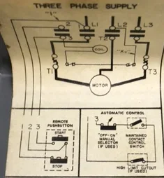
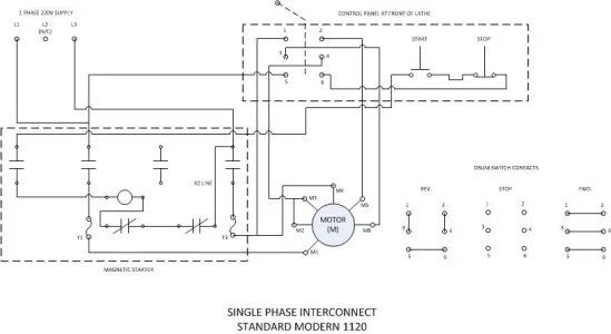
Here is the wiring diagram for the SM1120. It has the exact same controls (minus the door safety switch) as your 9“ Utilathe. It shows 3 phase motor(s), but that does not matter. Just use two (L1 & L3) of the lugs of the contactor instead of three. Make sure the “heaters” can handle the current of your single phase motor. Get properly rated ones once you have the circuit established and are ready to connect the load. Wire the door safety switch in series as the first item in your control circuit. Test everything with low voltage DC.
View attachment 21977
Just use two (L1 & L3) of the lugs of the contactor instead of three.
By doing this you bypass the two normally closed switches in the line between L2 and the coil.
but take the output from T3 and connect it to L2 (thus powering the coil) and connecting the output of T2 to to contact 1) of the drum switch.


make sure your 'motor starter heaters' in the AB switch are the right spec for your motor/phase. Thats something I had to change up.
Tecnico, if the motor has a fan with a shield around/over it, check that first for making the "noise" when slowing down. Also take a good look around the drive end of the motor and driven shaft/ pulley( belt drive). It save a lot of work (or add some). A chip, etc. maybe rubbing, dragging at various rpms causing noise. Sometimes things move when slowing or speeding up.
Hope fully not a bearing!
