

-
Scam Alert. Members are reminded to NOT send money to buy anything. Don't buy things remote and have it shipped - go get it yourself, pay in person, and take your equipment with you. Scammers have burned people on this forum. Urgency, secrecy, excuses, selling for friend, newish members, FUD, are RED FLAGS. A video conference call is not adequate assurance. Face to face interactions are required. Please report suspicions to the forum admins. Stay Safe - anyone can get scammed.
You are using an out of date browser. It may not display this or other websites correctly.
You should upgrade or use an alternative browser.
You should upgrade or use an alternative browser.
Working on my South Bend 9C
- Thread starter Golem Pens
- Start date
Golem Pens
Michael
I have ordered an alignment rod (since I really outta have one) and hopefully it's not trash.
Potentially eyeing this as a close to affordable chuck option https://www.ebay.ca/itm/352323748306
Potentially eyeing this as a close to affordable chuck option https://www.ebay.ca/itm/352323748306

BaronJ
Ultra Member
Hi Micheal,I follow the crude sketches and error stacking but not so much how the different probe types fit in. The question I jump to is how do I eliminate/check those variables to narrow it down...
The flat bit that Peter shows is called an "Elephants Foot" !
Not difficult to make and will allow you to measure accurately the position of a curved surface.
A hole drilled in a bit of bar that fits over the gauge plunger. Just like the drawing !
Golem Pens
Michael
While I wait for the alignment bar to arrive Wednesday, I wanted to check the collet chuck alignment, just to be sure. Well, it does seem about as good as I can expect, phew.


Yes looks like about 0.0004" TIR from where I'm viewing which is great. I've kind of lost track what exactly you are insertng & testing, but generally an ER collet itself should be about the same runout so I'd guess collectively you would be in the 0 - 0.001" clamping on a perfectly true dowel pin. So try that next, ideally on the same collet size you are using. If you part is measuring something substantially more than 0.001" its likely not circular/concentric. Now this holds true by positioning the DTI ball right close to edge of the collet. If you have a healthy part stickout & the part is cocked for whatever reason, it could measure runout because of that angle. If the collet was not quite tight enough or the part had a slight taper... Again, ER is better than other holding systems in this regard because it has more longidudenal contact area over its grip (as opposed to 5C which is more of a nose pinch). Only other thing I can think of is if your part is a hollow tube & tightning it in the collet manages to distort the wall thickness. This is typically a 3J or 4J chuck issue though. Again, ER is better here because it is a relatively radial grip force, meaning equal pressure through each of its leaves.
All you can do is add one step or part at a time & try & isolate it. But looks like you have eliminated the ER seat. Last question, you are snapping the collet into the end cap ring correctly each time before tigtening right? I dont even think it will work otherwise but just mentioning because some guys seem to have more stubborn rings.
All you can do is add one step or part at a time & try & isolate it. But looks like you have eliminated the ER seat. Last question, you are snapping the collet into the end cap ring correctly each time before tigtening right? I dont even think it will work otherwise but just mentioning because some guys seem to have more stubborn rings.
Last edited:
Golem Pens
Michael
@PeterT yes there has been a lot going on... I'm glad that stepping back to the start is helpful.
I don't have a true precision ground pin, but I used the shaft of a decent reamer as an analog the other day. Not the same collet unfortunately, but a close size at least. Not sure if this is accurate enough though.
And yes, the collets ARE properly seated!
Control - 0.496" reamer shaft
CRA - 0° to collet mark: https://photos.app.goo.gl/S77tF4TMD1rcke8R8
CRB - 180° to collet mark: https://photos.app.goo.gl/rr7EV76A5m1GT19eA
To my eye these are the same, about 0.0010 TIR. Indicates that the collet/spindle/machine is okay.
I don't have a true precision ground pin, but I used the shaft of a decent reamer as an analog the other day. Not the same collet unfortunately, but a close size at least. Not sure if this is accurate enough though.
And yes, the collets ARE properly seated!
Control - 0.496" reamer shaft
CRA - 0° to collet mark: https://photos.app.goo.gl/S77tF4TMD1rcke8R8
CRB - 180° to collet mark: https://photos.app.goo.gl/rr7EV76A5m1GT19eA
To my eye these are the same, about 0.0010 TIR. Indicates that the collet/spindle/machine is okay.

To my eye these are the same, about 0.0010 TIR. Indicates that the collet/spindle/machine is okay.
Yes, I agree with your conclusions. Nonetheless, I wonder about the 1 thou. Not because it's a problem but rather to help us understand your machine and your setup. Does the high spot stay with the reamer shaft as you index it, or does it stay with the collet, or does it follow some other relationship?
Getting 1 thou at that much stick out without using some way to adjust axial alignment is very good. What is it like up close to the collet?
Another thing that might be worth exploring is the stiffness of your spindle. It's possible that the cutting forces are displacing the spindle a bit such that runout with no load is good but runout with cutting forces applied is not. If so, improving the runout takes a different direction than we have been discussing.
You can do this test by pulling or pushing your reamer shaft as consistently as you can while measuring the play at the collet face on the same plane as the load. This should be done at least every 90 degrees - more if you find big differences. Don't let the results scare you. It's normal to get much bigger numbers than in the unloaded tests you have done. You just want to know what it is like.
Basically, I'm trying to understand why your reamer numbers are so much better than your mandrel numbers.
Golem Pens
Michael
I will test more thoroughly with the reamer and report back. Alignment tool comes tomorrow so hopefully that clarifies any potential tailstock shenanigans.
Golem Pens
Michael
Just to confirm, measuring the play/movement of the face of the collet itself, or of the rod close to the collet?You can do this test by pulling or pushing your reamer shaft as consistently as you can while measuring the play at the collet face on the same plane as the load.
Just to confirm, measuring the play/movement of the face of the collet itself, or of the rod close to the collet?
Of the rod close to the collet.
Golem Pens
Michael
Okie dokie, we have more data @Susquatch
- This was using the same 7/16" reamer shaft as before.
- Since I mounted the DTI on my carriage, I checked the neutral height at both measurement points with the spindle not moving. At 4" out, it was .001"lower. I also did the same, and a rotating test while supported by a live center, and there was >.0005" runout. So I imagine that other reading is due to bed wear, not a warped reamer shaft.
- Three measurements were taken:
1) Deflection measured at collet.
2) Runout at collet.
3) Runout 4" from collet (as far as I can go, and realistically the farthest I would be out with any regularity.
- This was using the same 7/16" reamer shaft as before.
- Since I mounted the DTI on my carriage, I checked the neutral height at both measurement points with the spindle not moving. At 4" out, it was .001"lower. I also did the same, and a rotating test while supported by a live center, and there was >.0005" runout. So I imagine that other reading is due to bed wear, not a warped reamer shaft.
- Three measurements were taken:
1) Deflection measured at collet.
2) Runout at collet.
3) Runout 4" from collet (as far as I can go, and realistically the farthest I would be out with any regularity.
| Index location | Deflection at collet | Runout at collet | Runout at 4" |
| 0° | .002" | .0005" | .003" |
| 45° | .002" | .001" | .004" |
| 90° | .002" | .001" | .004" |
| 135° | .003" | .001" | .006" |
| 180° | .0025" | .001" | .003" |
| 225° | .003" | .001" | .005" |
| 270° | .0025" | .0005" | .006" |
| 315° | .002" | .0005" | .004" |
Okie dokie, we have more data @Susquatch
None of your results in the first two columns are particularly worrisome. They are all reasonable for your machine.
The deflection is consistent within a thou which suggests that cutting loads do not contribute to your part concentricity issues.
However, the measured runout at 4" does suggest a spindle or collet axial concentricity concern. In particular, the fact that runout is not cyclic and consistently high makes me wonder about the reamer shaft itself.
Could you please redo the 4" stickout test but tell us both the high and the low number for each angle as opposed to just the runout?
Golem Pens
Michael
None of your results in the first two columns are particularly worrisome. They are all reasonable for your machine.
The deflection is consistent within a thou which suggests that cutting loads do not contribute to your part concentricity issues.
However, the measured runout at 4" does suggest a spindle or collet axial concentricity concern. In particular, the fact that runout is not cyclic and consistently high makes me wonder about the reamer shaft itself.
Could you please redo the 4" stickout test but tell us both the high and the low number for each angle as opposed to just the runout?
| Index angle | Low | High |
| 0° | -0.0025" | +0.003" |
| 45° | -0.0025" | +0.003" |
| 90° | -0.002" | +0.002" |
| 135° | -0.0025" | +0.003" |
| 180° | -0.0035" | +0.003" |
| 225° | -0.004" | +0.003" |
| 270° | -0.004" | +0.003" |
| 315° | -0.003" | +0.003" |
Index angle Low High 0° -0.0025" +0.003" 45° -0.0025" +0.003" 90° -0.002" +0.002" 135° -0.0025" +0.003" 180° -0.0035" +0.003" 225° -0.004" +0.003" 270° -0.004" +0.003" 315° -0.003" +0.003"
OK, I asked that wrong.. My apologies. I think we have a significant communication gap. I don't even know how you got high's and lows for one angle. Is it changing each time?
What I want is the actual number on the DTI, not the runout. This might indeed be a high and a low if the numbers change for each reading of a repeat reading for the same angle.
I might be trying too hard to explain and thereby making things worse. Please force me to choose words that make sense to you.
Perhaps it would help if I told you what we are trying to learn.
First, we are trying to determine if your reamer is really round. It isn't a gauge pin so there is no guarantee that it is. And I don't think you have the metrology to measure it other than in the lathe.
The other thing we want to do is evaluate your axial concentricity. In other words, is the central axis of the pin concentric with the axis of your spindle?
Golem Pens
Michael
Ah dear, sorry. Let me just illustrate where that came from in case that makes sense, before changing things.
I adjusted the DTI so that I had the zero point as close to the middle of travel as possible, like below. I did NOT adjust the dial in between measurements, the middle at zero was quite consistent at all angles.
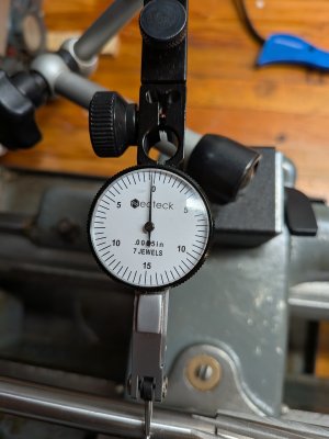
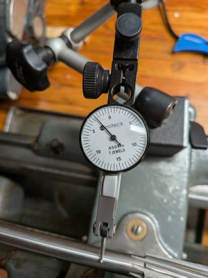
So, I came to, for example a low of -0.0025", from the following image, where the left extreme reading is 5 ticks off zero (-5 x 0.0005 = -0.0025).
And then the opposite for the high:
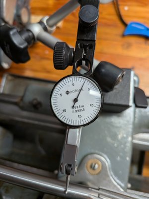
Put another way, what I called -0.0025 to 0.0025" would be equivalent to a low of 5 and a high of 10 on this particular dial. I just tried to convert it to a standard measure.
Does that make this data make sense at all?
I adjusted the DTI so that I had the zero point as close to the middle of travel as possible, like below. I did NOT adjust the dial in between measurements, the middle at zero was quite consistent at all angles.
So, I came to, for example a low of -0.0025", from the following image, where the left extreme reading is 5 ticks off zero (-5 x 0.0005 = -0.0025).
And then the opposite for the high:
Put another way, what I called -0.0025 to 0.0025" would be equivalent to a low of 5 and a high of 10 on this particular dial. I just tried to convert it to a standard measure.
Does that make this data make sense at all?
BaronJ
Ultra Member
Hi Michael, Susquatch,
Your DTI needs to be on to highest point of the work ! Looking at that picture suggests that it is beyond the center of the reamer shaft. Move the DTI back and stop at the highest reading. That should now be the center point. Also each division of your DTI is equal to half a thou. I fasten a dial gauge in the tool holder and use an elephants foot to get over not having the plunger dead on center. If you look at Peter's drawing you will see what I mean.
Making a measurement close to the Collet face should not show any real movement, if it does then it might suggest that the spindle needs adjusting. I check mine with a one inch diameter bar held in the chuck, I get no or very little movement. Bear in mind that I run a Myford lathe and the front spindle bearing is a bronze cone. Adjustment is from the tail of the spindle via a pair of ball bearings !
Your DTI needs to be on to highest point of the work ! Looking at that picture suggests that it is beyond the center of the reamer shaft. Move the DTI back and stop at the highest reading. That should now be the center point. Also each division of your DTI is equal to half a thou. I fasten a dial gauge in the tool holder and use an elephants foot to get over not having the plunger dead on center. If you look at Peter's drawing you will see what I mean.
Making a measurement close to the Collet face should not show any real movement, if it does then it might suggest that the spindle needs adjusting. I check mine with a one inch diameter bar held in the chuck, I get no or very little movement. Bear in mind that I run a Myford lathe and the front spindle bearing is a bronze cone. Adjustment is from the tail of the spindle via a pair of ball bearings !