• Scam Alert. Members are reminded to NOT send money to buy anything. Don't buy things remote and have it shipped - go get it yourself, pay in person, and take your equipment with you. Scammers have burned people on this forum. Urgency, secrecy, excuses, selling for friend, newish members, FUD, are RED FLAGS. A video conference call is not adequate assurance. Face to face interactions are required. Please report suspicions to the forum admins. Stay Safe - anyone can get scammed.

Working on my South Bend 9C

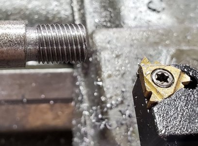
Michael was over yesterday for an ELS demo. Didn't cut a proper exit relief and chipped the carbide tool bit as it ran into the tapered shoulder. Also set the thread depth for a 5 TPI thread rather than 20 TPI since we were trying a 4 start thread.

Had to go do it again this morning just to ensure I hadn't totally lost my mind. New tool bit insert. 200 RPM. Soft crappy steel. Filed the burrs off the edges with a fine file. Maybe too much but it came out looking nice given the material. Thread length is 0.5" At 5 TPI that's 2.5 turns.

5TPI-4Start.jpg
 
Wooo nicely done!
I should probably make a nut for it but then what... No use for it and can't see a use for something like that. But it was fun doing it again and correctly this time. Really should replace the cross slide nut to remove backlash and add a stepper motor to the X axis.
As we discussed yesterday, those small dials are hard to read. That or add a DRO to both axis.
 
No use, just practice/the interest.

I should also look into a new crosslide nut as well...
DRO would be nice, but with bigger dials I feel it would be less necessary.

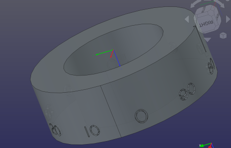
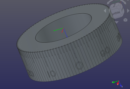
But speaking of dials, I won't pay this much but maybe I can model my own and get someone to print:

And of course I want to extend the tailstock travel still...
 
Okay so I figured a good reamer should be decently straight. I apologize in advance for the video, I really need to get a way to hold my phone...

But that shows .0005" total runout, if I did and read this right: https://photos.app.goo.gl/Co6RVsxyHxoeaJky9

So that's good!

One of the mandrels is okay, the other is no bueno. I guess try them again, but between centers this time. Maybe go to steel?
 
Ya i was wondering if you slipped a decimal place in your original TIR description
This is from yesterday with the DI and the better mandrel. Not a 1-1 comparison obviously but where that number came from https://photos.app.goo.gl/rZD1ehWm12FuN5iL8

This is the better mandrel: https://photos.app.goo.gl/DcKDQqTJJHbMJVHh6

This is the worse mandrel: https://photos.app.goo.gl/Qy2CUANtWgYTEkv18

The issue I notice in the hand is when the two pieces are threaded I can feel a "low" point between their ODs
 
Some final shenanigans to resolve, but modelling bigger lathe dials...
 

Attachments

  • Screenshot 2026-11-06 at 10.07.13 PM.png
    Screenshot 2026-11-06 at 10.07.13 PM.png
    366.2 KB · Views: 1
  • Screenshot 2026-11-06 at 10.07.22 PM.png
    Screenshot 2026-11-06 at 10.07.22 PM.png
    481.5 KB · Views: 1
This is from yesterday with the DI and the better mandrel.

Two things Michael.

1. That DTI should be mounted such that the DTI needle drags lengthwise on the mandrel, not sideways. I'm not saying that sideways is wrong, but it does load the DTI in a way that bends the needle and stresses the mechanism. I only load them the way you did when I have no choice.

2. The way that you describe these tests suggests that the mandrels were made previously in another operation and then remounted for evaluation. That works if everything is perfect. But it rarely is. Usually, the runout in the various parts stack up and conspire to bite you. Looking at your tests, one might conclude that one mandrel is better than the other. But how do you know that? Perhaps it is only mounted in a way that reduces the stack up. In effect, various runouts cancel. Have you tried re-indexing the mandrels in the collet? Have you tested the mandrel runout on a surface plate? If you have not evaluated this then how do you know where the runout is coming from? It might not be a bad mandrel, it might be a bad setup. Or it might be a bad setup when the mandrel was made.

There are many ways to reduce runout. But the most commonly used approach is a physical offset like that provided by 4 jaw chucks or SetTru chucks. In both cases, you might get alignment at one length, but not at another.

Most of my setups take very high advantage of indexing. Record or mark the position at the time the part was made and then reposition it so it is positioned that same way in use. But some parts need to be realigned each time they are used because they are centered only at one point in their axis when they were made. When this happens, they need to be axially aligned each time they are used. Because this is so important in my own smithing hobby interests, I actually made several specialized chucks to deal with it. You might search on "align" in the members only subforum to get a sense of this and why it's important. Your mandrel is long enough that this could well be an issue for you.

 
@Susquatch

1) Humbug I always mount the DTI in the wrong orientation. Gonna make a big sign to hang over the lathe. I'll do that and run again.

2) Won't respond to all points, but aye... much work to do there. I'll press on the indexing aspect first since that's what I can do (multi-faceted alignment between mandrel, collet and chuck, oh my). Regrettably no surface plate, or jawed chuck to throw in the mix yet.

More faffing and a report to come.
 
Back
Top