TIR drift of Set-Tru Chuck

trevj

Ultra Member
Not at you , or about you, as much as about the subject matter of the OP, and the expectations, apparently, that there was NOT going to have to be any adjustment from part to part. On something with a wide open set of tolerances, it may well be, that the adjustment of a Set-true type of 3 jaw, will still get you there, but it becomes much like the problem of the Precision Bench level, and attempting to rely on it for setting up a machine in an environment patently unsuited for it's use (ie: most Home Shops!), that the difference between what you expect, and what you get, is not on the equipment, so much as on the expectations (usually wrong) of the user.

As for Pro, not really. I did it for a living for a while, and I taught the basics to a bunch of folks over the years. Been metalworking one way or other starting in grade school. Honestly, misplaced expectations are the hardest thing to get folks past, once you convince them that no matter how many drawers they may look in, we were not actually hiding away any tooling that would make them not have to practice!

I live on a farm, but won't call myself Farmer, as I don't have to make a living at it! Thankfully!
 

Dabbler

ersatz engineer
User expectations are sometimes hard to argue with. Just because a chuck is toleranced to half-thou, or you can set the TIR to less than that doesn't mean, for practical purposed that you need those close tolerances. Most of my machining is probably around +/- .002, but when I reed to, I can do sub-tenths. But the investment of time and additional operations and methods isn't worth it for a part where .003 out won't matter at all.

I really like set-tru style chcks. When I need to I can get that half-thou repeatability. But for really accurate stuff, there is nothing like a collet. For any better, custom fixturing is desirable.
 

Susquatch

Ultra Member
Administrator
Moderator
Premium Member
Not at you , or about you, as much as about the subject matter of the OP, and the expectations, apparently, that there was NOT going to have to be any adjustment from part to part. On something with a wide open set of tolerances, it may well be, that the adjustment of a Set-true type of 3 jaw, will still get you there, but it becomes much like the problem of the Precision Bench level, and attempting to rely on it for setting up a machine in an environment patently unsuited for it's use (ie: most Home Shops!), that the difference between what you expect, and what you get, is not on the equipment, so much as on the expectations (usually wrong) of the user.

OK. I accept that.

But I don't think @PeterT (the OP) expectations were out of line either. But perhaps my opinion is highly influenced by the fact that I've gotten to know him a bit better through our many debates and discussions of complicated issues. His post started out just wondering why a set-tru would drift just sitting on the shelf but not while mounted on his lathe. That led to other questions and a discussion about how set-tru chucks are used. Maybe I shouldn't speak for him but I know he also understands the limitations you described quite well.

The discussion about set-tru maintenance adjustments was mostly a side issue and a distraction that fell out of watching Gotteswinter's video. The intent there was never to suggest that once set, a set-tru could permanently replace a 4-jaw or a collet chuck. Only that its an improvement over a regular 3Jaw for jobs that don't require more than a few thou of precision.

Rather than beat that dead horse over again, a very useful question for you to take on for everyone is the original question of the post. Why would a Set-tru chuck drift over time on the shelf but not on the lathe?

There are lots of possibilities ranging from storage conditions to mounting stresses and variations to plain old observational errors. In many ways, I am already happy with the answers. But it's also possible that there is a simple obvious light bulb answer that hasn't jumped out at the rest of us just yet.

Any insights? Might help to review the first few posts in this thread.
 

Dabbler

ersatz engineer
But I don't think @PeterT (the OP) expectations were out of line either.
I agree. A chuck that wanders around its TIR is unusual. It is in line with castings that never seem to quiet down, even after a lot of aging.

-- and Peter needs to do very accurate work in building his engine. His work is superb!
 
I'm going to make comment here (maybe a repeat of someone else).

Has anyone considered that when changing chucks they are not remounted in the same orientation mounting pin wise. While the rings are concentric, they may be off in a direction or two, same with the mating surface. In one orientation they zero, in another they don't. Depending on which "D" mount you have increases the chance on variation.

I have marked mine to ensure change for change always mounts on the same pin location to reduce this chance.
 

PeterT

Ultra Member
Premium Member
Another model engineer guy I know in the States recently mentioned the exact same ST drift issue & amount that I did, also Bison, also 6" 6J. We chatted offline, he is very experienced & I trust his measurements. My chuck seems to have settled down to what I'd call within 0.001" over say a couple months which I attribute to minimizing set screw torque vs. prior when I had 'more' torque. Body distortion with set screw torque is real, Renzetti demonstrated it with DTI in the video I referenced earlier in the post. Which is why he went through pains to modify the backplate & other changes. Now does a lighter walled, smaller diameter chuck distort even more with same torque? Hard to know for sure but probably. Makes sense. The Bison 5C ST chuck has 4 screws, I'll confirm but I recall the 6J has 6 so I would have thought more evenly distributed adjustment load?

@Degen yes I always index the backplate D-pins to same spindle reference position once I find the least runout position.

Standard Bison verbiage. Now nowhere do they actually say 'for how long' the runout is to remain. You know what they say about assuming LOL.
Bison SET-TRU Chucks can give your lathe the accuracy of a tool room lathe. Once dialed in you can count on .0003" total indicator run out (radial) and .0001 total indicator run out (axial).

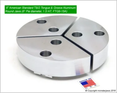
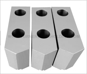
Without turning this into a work holding post, there are other ways to get improved repeatable accuracy with a 3J chuck or for more challenging part geometry. Machinable soft jaws, either straight or pie, could help. Yes, collets are great, but only up to typical 1" OD range they encompass. I find that thin walled tube like parts or thin washer like parts to be finicky especially in softer alloys. But maybe soft jaw could be same principal for through bores as long as jaws are preloaded like you see for jaw grinding? But soft jaws are kind of a $$ disposable item whereas a ST is more like a general work holder that can be dialed in the final amount. Glue methods can work on washer shapes but that can be finicky too & PITA for more than a few parts, especially if heat is required to de-bond. I knew if I procrastinated making my own soft jaws long enough I'd find them at a price I could swallow (the ones on right are 29USD for set of 3). I'll report back when they arrive. Actually I want to use them more as a jaw base for matching footprint sacrificial material to be bolted on with smaller fasteners out of the way of the big counterbore holes. To be continued.

1694399070249.png 1694399103871.png
 
Last edited:

trevj

Ultra Member
I'm going to make comment here (maybe a repeat of someone else).

Has anyone considered that when changing chucks they are not remounted in the same orientation mounting pin wise. While the rings are concentric, they may be off in a direction or two, same with the mating surface. In one orientation they zero, in another they don't. Depending on which "D" mount you have increases the chance on variation.

I have marked mine to ensure change for change always mounts on the same pin location to reduce this chance.
That is a very likely culprit, as is the possibility that there are chips in places that were not considered, like in the cam areas, if a camlock chuck, or simply stuck to parts of the lathe or chuck, in a manner than makes the results not repeatable. Include the raised areas around bruises from such, in the chuck mounting system. If that confuses anyone, center punch a dot on a relatively flat piece of material, then use a block with sandpaper, or a known decent file, the level the surface again, and you will clearly see the displaced material! Add to that, that removing and re-installing such parts, can re-displace, that same material, dependent on the forces used... Making the results now, different than the results the next time...

I have known guys to both mark the best orientation to use when mounting their chucks, as well as to mark the 'most accurate' key-hole, on their chucks. But I can't be bothered.

With a keen eye on the extra amount of time that needs be spent dicking with stuff that really does not put forth a relatively reliable end result, I simply stick to what I have, and knowing what that gear's limits are, and adjust as needed, when needed, for those few times that I actually NEED accuracy, and cease to worry about the run out, on things that do not, generally, need such fiddly effort.

I will clarify a little on my low opinion of Precision Levels. You lot that live in Bedrock Country, out on the Canadian Shield, can disagree, but that was never me. I lived in houses that ran up and down like the tides, over the seasons, and had I ever tried to level a Lathe with an actual precision level, all it meant would be that I was going to be doing it A LOT! As a case in point, the house I lived in, in Cold lake Alberta, rose and fell throughout the year (expansion and contraction of clay mud subsoil) enough that the drywall tape down the ceiling in my hall upstairs, could be noted to flex from providing a square corner to a very rounded one. The bathroom vanity would pull away from the wall about a half inch over the year, and make it's way back under the well thought out (because it hid said movement!) trim that was around the backsplash. But by setting my lathe up to cut straight and parallel, and not stressing over what a damn Level had to say, it never bothered me in the least! A carpenter's level, is a great tool, but only if you cannot tell by looking, why the coolant refuses to run to the 'drain' end of the chip tray! :)
 

PeterT

Ultra Member
Premium Member
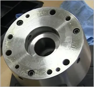
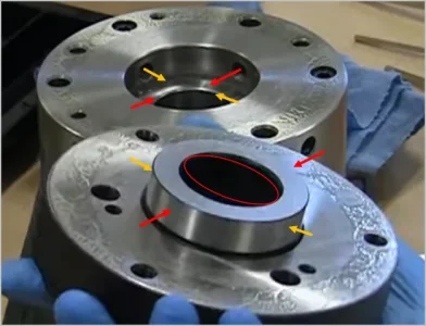
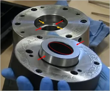
This shows a Precision Mathews Set-Tru type 5C collet chuck being disassembled & maybe better depicts what I was visualizing might be going on. There is a small annular gap between the adjustment backplate & the chuck body to allow ST adjustment. The 4 set screws dial in the chuck by pinching in opposing direction, same principle as a 4J chuck. But this only happens when the chuck is on the spindle nose, so there is something solid within the center hole. All good so far. What I was wondering out loud to myself is once removed from lathe, there actually isn't a lot of annular meat in the center ring. So if the screws were excessively torqued or torqued unbalanced, then may be conceivable that the ring becomes distorted over time as it stress relieves. Red ellipse shows exaggerated distortion. If that happens, then it would make sense that the chuck it may be out some minor amount upon remounting. I can't visualize that my D1-4 spindle nose goes in from the opposite side very far though so one would think it wuld take a lot of egging before the chuck would see runout. I'll have to examine this more closely. Renzetti's clip showed the chuck body distorting as measured from the outside. the chuck is connected to the plate so I think it amounts to the same thing?

Anyhoo, for now, seems like lighter screw torque on the set screws seems to be helping. One day when I buy a torque wrench I'll see what's actually happening with the front retention bolts.

1694407057667.png 1694407552766.png


Attachments

  • 1694406440798.png
    1694406440798.png
    742.9 KB · Views: 2

Susquatch

Ultra Member
Administrator
Moderator
Premium Member
So if the screws were excessively torqued or torqued unbalanced, then may be conceivable that the ring becomes distorted over time as it stress relieves.

Is that chuck cast iron by any chance? If so, then I think what you surmise might be possible. On the other hand, steel doesn't do that - at least not on a time scale or temperature environment that we humans would care about.

This business about contamination inside on the camlocks is an interesting thought. But I doubt it really matters if the nose and registration surfaces are clean and properly dimensioned. If that is not the case, then I think it could matter.

FWIW, I clean the registration surfaces on EVERY JOB no matter how finicky the task. Most of us have seen what happens with just one careless moment. So even on a farm repair where a 16th is good enough, the registration surfaces get cleaned.

Similarly, every chuck I own or make gets indexed and marked so it is always installed the same way every time it is used. I bet all of us do that.

First I ever heard of indexing the tightening sequence. Makes some sense, but by the time it comes to matter I've already switched to a four jaw or a spider. For me, indexing the camlocks seemed like a freebee improvement. But I agree with trevj, indexing the tightening sequence seems quite excessive for the rewards.

You lot that live in Bedrock Country, out on the Canadian Shield, can disagree, but that was never me. I lived in houses that ran up and down like the tides, over the seasons, and had I ever tried to level a Lathe with an actual precision level, all it meant would be that I was going to be doing it A LOT!

I think that's a valid thought. But I don't think this is Peter's case. His chuck is drifting on a shelf.

In industry, this issue is dealt with by pouring concrete in large enough reinforced masses such that they are either floating or seismic. The subsoil can do what it wants but the mass will find its own level. The last office tower I built was basically a huge ship floating on clay. The ground could move all it wanted and the ship stayed level. This isnt really practical for a hobbiest, but the principle can still apply. Precision lathes are often used on ships but manage to work just fine because true level isn't really the goal. Relative level (bed twist) is.

Anyway, I think this is a red herring in Peter's case. Just an interesting discussion point.

Anyhoo, for now, seems like lighter screw torque on the set screws seems to be helping.

I'm really curious to know if your chuck is cast or steel. I looked at Bison's literature and apparently they make both with steel being twice the price of cast.

One day when I buy a torque wrench I'll see what's actually happening with the front retention bolts.

You don't have a torque wrench???? I confess I am in shock....... LOL!

Despite my otherwise anal approach to torque, I don't tighten my chucks with a torque wrench. The only time I ever considered it was back in a thread a year or two ago about frozen stuck camlocks. That made me gunshy for a few weeks, but I'm over it now. The short handles on a camlock T-Wrench do a pretty good job of limiting torque. And in my opinion, the registration design of a properly made chuck doesn't need it.
 
That is a very likely culprit, as is the possibility that there are chips in places that were not considered, like in the cam areas, if a camlock chuck, or simply stuck to parts of the lathe or chuck, in a manner than makes the results not repeatable. Include the raised areas around bruises from such, in the chuck mounting system. If that confuses anyone, center punch a dot on a relatively flat piece of material, then use a block with sandpaper, or a known decent file, the level the surface again, and you will clearly see the displaced material! Add to that, that removing and re-installing such parts, can re-displace, that same material, dependent on the forces used... Making the results now, different than the results the next time...

I have known guys to both mark the best orientation to use when mounting their chucks, as well as to mark the 'most accurate' key-hole, on their chucks. But I can't be bothered.

With a keen eye on the extra amount of time that needs be spent dicking with stuff that really does not put forth a relatively reliable end result, I simply stick to what I have, and knowing what that gear's limits are, and adjust as needed, when needed, for those few times that I actually NEED accuracy, and cease to worry about the run out, on things that do not, generally, need such fiddly effort.

I will clarify a little on my low opinion of Precision Levels. You lot that live in Bedrock Country, out on the Canadian Shield, can disagree, but that was never me. I lived in houses that ran up and down like the tides, over the seasons, and had I ever tried to level a Lathe with an actual precision level, all it meant would be that I was going to be doing it A LOT! As a case in point, the house I lived in, in Cold lake Alberta, rose and fell throughout the year (expansion and contraction of clay mud subsoil) enough that the drywall tape down the ceiling in my hall upstairs, could be noted to flex from providing a square corner to a very rounded one. The bathroom vanity would pull away from the wall about a half inch over the year, and make it's way back under the well thought out (because it hid said movement!) trim that was around the backsplash. But by setting my lathe up to cut straight and parallel, and not stressing over what a damn Level had to say, it never bothered me in the least! A carpenter's level, is a great tool, but only if you cannot tell by looking, why the coolant refuses to run to the 'drain' end of the chip tray! :)
You have the right idea, but to further clarify the ideal method of dealling with this.

Floating slabs as a machinery basis. Rigid enough not to flex under movement or load. The idea is you do your initial setup accurately and precise as you base is solid. No matter how your base is moved by the surrounding environment the accuracy and precision remains regardless of the current orientation. The slab is the reference nothing else matters.

It should be mentioned that the biggest drawback of this method is the slab size and strength.
 

trevj

Ultra Member
You have the right idea, but to further clarify the ideal method of dealling with this.

Floating slabs as a machinery basis. Rigid enough not to flex under movement or load. The idea is you do your initial setup accurately and precise as you base is solid. No matter how your base is moved by the surrounding environment the accuracy and precision remains regardless of the current orientation. The slab is the reference nothing else matters.

It should be mentioned that the biggest drawback of this method is the slab size and strength.
I agree with you entirely, on the floating slab concept, but how many home-shop guys really can afford that as an option?Most run what they got, rather than cutting holes in the basement (or garage) floor to support their hobby tools! I recall a small (5 or 6 foot arm) Radial Arm Drill being installed in a shop, and recall clearly, how very large and deep the prescribed Pad under it was. 4 feet deep, and extending well out past the footprint of anywhere around the drill's reach in all directions.

If all the cleanliness issues and the potential damage they can create, are off the table as suspects, it pretty much seems to be that the iron (if Iron) having some fair amount of residual stresses built in to it, would be a high probability.
 

Susquatch

Ultra Member
Administrator
Moderator
Premium Member
it pretty much seems to be that the iron (if Iron) having some fair amount of residual stresses built in to it, would be a high probability.

A small nuance which I'd bet you understood and meant. But perhaps not everyone will.

This isn't really residual stress. It's stress imposed by very tight jack screws.

The cast iron (if that's what it is) doesn't care if the stress is residual or imposed. It can relax over time to relieve the stress.
 
I agree with you entirely, on the floating slab concept, but how many home-shop guys really can afford that as an option?Most run what they got, rather than cutting holes in the basement (or garage) floor to support their hobby tools! I recall a small (5 or 6 foot arm) Radial Arm Drill being installed in a shop, and recall clearly, how very large and deep the prescribed Pad under it was. 4 feet deep, and extending well out past the footprint of anywhere around the drill's reach in all directions.

If all the cleanliness issues and the potential damage they can create, are off the table as suspects, it pretty much seems to be that the iron (if Iron) having some fair amount of residual stresses built in to it, would be a high probability.
The irony is if you've mounted on the basement/garage/shop slab you've likely accomplished this as it usually a separate isolated component of the foundation even if they look attached, for the same reasons we worry about.

So as the saying goes, set it and forget it. ;).
 

trevj

Ultra Member
A small nuance which I'd bet you understood and meant. But perhaps not everyone will.

This isn't really residual stress. It's stress imposed by very tight jack screws.

The cast iron (if that's what it is) doesn't care if the stress is residual or imposed. It can relax over time to relieve the stress.
In truth, I was largely considering castings that were subject to poor management, and then rushed through production, without either getting aged out, or heat treated for the purpose of relieving the tied up stresses, but I can see that getting heavy handed with the wrench could add yet another changeable to consider.

In my view, tuning any of the adjustable mounts should be a VERY low effort job, with a light touch on all the screws, rather than say, running around a four jaw and simply using the flex to adjust that last tiny hair out of the part! The fixing bolts on the adjustable, should provide only a tight enough grip that it actually does not flop around, and the adjustments shold take almost no effort to produce results, I would not go so far as to suggest thatteh screws need be backed off once adjusted, but it does seem to me that the fixing bolts are what holds the adjusted chuck in place on it's mount, not the screws used to do the fine adjustments. No?
 

trevj

Ultra Member
The irony is if you've mounted on the basement/garage/shop slab you've likely accomplished this as it usually a separate isolated component of the foundation even if they look attached, for the same reasons we worry about.

So as the saying goes, set it and forget it. ;).
Interestingly, neither my garage floor, nor my basement floor, ever showed any signs of movement in relation to the vertical portions of the foundations. I looked. Hard!

Had a supervisor that spent nearly $80K trying to 'fix' his house, rather than simply accepting that he was stuck with this annual cycle. In the end, he was very good for the contractors he hired, he spent all the money he should have gained in equity while he lived there, and when he moved out, the house still rose and fell as it had before...
 

Susquatch

Ultra Member
Administrator
Moderator
Premium Member
In truth, I was largely considering castings that were subject to poor management, and then rushed through production, without either getting aged out, or heat treated for the purpose of relieving the tied up stresses, but I can see that getting heavy handed with the wrench could add yet another changeable to consider.

In my view, tuning any of the adjustable mounts should be a VERY low effort job, with a light touch on all the screws, rather than say, running around a four jaw and simply using the flex to adjust that last tiny hair out of the part! The fixing bolts on the adjustable, should provide only a tight enough grip that it actually does not flop around, and the adjustments shold take almost no effort to produce results, I would not go so far as to suggest thatteh screws need be backed off once adjusted, but it does seem to me that the fixing bolts are what holds the adjusted chuck in place on it's mount, not the screws used to do the fine adjustments. No?

Yes. I agree on all counts.

I was just focussed on the downside of very tight jack screws. They would stress the cast iron (if that's what it is) and then cast iron, acting like cast iron does, would likely tend to release this stress over time - which is exactly what Peter is seeing.

To be clear though, this is not a closed book for me. It's just one very plausible explanation that I am comfy with.

Still waiting for @PeterT to confirm the chuck material. With my luck, it will be steel.... LOL!
 

trevj

Ultra Member
Yes. I agree on all counts.

I was just focussed on the downside of very tight jack screws. They would stress the cast iron (if that's what it is) and then cast iron, acting like cast iron does, would likely tend to release this stress over time - which is exactly what Peter is seeing.

To be clear though, this is not a closed book for me. It's just one very plausible explanation that I am comfy with.

Still waiting for @PeterT to confirm the chuck material. With my luck, it will be steel.... LOL!
Nah. With luck, it (or at least, parts of it) will be iron, otherwise we have had a great conversation, but got no closer to sorting out the actual cause...
 

PeterT

Ultra Member
Premium Member
5C material mentioned in post #23
Chuck is forged steel & I believe backplate adapter is the same.
Bison 5C Set Tru Collet Chuck

6 jaw material
* Chuck body made of high quality Forged steel, is safe at high lathe speeds.
* Forged Scroll fully hardened with thread flanks ground on both sides for longer life and higher accuracy.
* Hardened and ground bushings are pressed into the pinion seats.
* 3 pinions are hardened and ground


PeterT

Ultra Member
Premium Member
Watch Renzetti's chuck demo of set screws. Discussion starts around 12:20. Not only does he show significant distortion of chuck body as set screws are only moderately tightened, he then locates the DTI 90-deg to the set screw area which is not being torqued but also feeling the effect, albeit to slightly less degree which is understandable. Its like pinching a hoola-hoop, it goes elliptical. This was a 8" chuck, presumably heavier walled body. As the axial bolts are tightened through the runout dial in ritual, which they need to be, the set screws have to overcome the increasing friction of chuck to backplate. That's what makes it kind of subjective to how much torque is appropriate. It depends on how tight the front axial bolts are.

His first mod is to replace the 'dust cover' backplate which is rather loose fitting, with a tight fitting plate, which acts like an intermediate bulkhead. The other mod is he drilled additional axial bolt holes to provide more force / even force retaining the chuck to the backplate. Now all of this is lathe in-situ where the spindle is providing support. I haven't seen too many people put the chuck back on while off the lathe for a period. But reading between the lines, its not too difficult to visualize the set screw stresses normalizing themselves.


Susquatch

Ultra Member
Administrator
Moderator
Premium Member
But reading between the lines, its not too difficult to visualize the set screw stresses normalizing themselves.

Unfortunately, I have the opposite feeling Peter. It's very hard to visualize the set screws stresses normalizing themselves in steel. Steel only does that at very high temperatures. I can't see it happening at all in your shop.

Back to the drawing board..... :(
 
Top