Tail Stock lock

Susquatch

Ultra Member
Administrator
Moderator
Premium Member
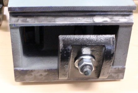
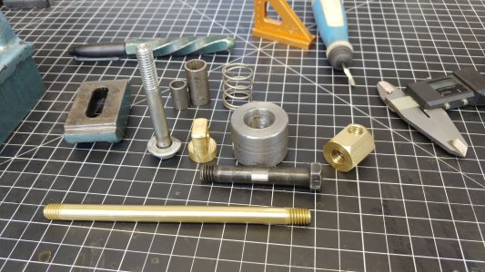
I'll take a better picture when the tee block is out. It's a cast iron part & has kind of a relief profile molded in the lower surface for the nut to hide up into. So the net thickness is probably 1/2". Its goofy, almost like it was intended for a smaller lathe.

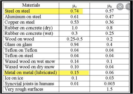
Providing more clamping area between the tee plate to the way undersides would increase friction holding force for the same lever cam force, which I think is fine. Just spit balling numbers, the current contact area is maybe 3" x 0.25" x 2 = 1.5 in2 vs a larger plate say 6" x 0.75 x 2 = 9 in2 (6x more area). I seem to recall the underside bed rail surfaces may not be ground & the existing plate is rough milled, so also contributes to reduced friction. Its only under heavy drilling that the TS wants to slide backwards. I guess if I was ambitious I could find something like brake liner material in strip form & bond it to the T-plate groove, but it's probably overkill.

I don't think your net thickness is a valid way of looking at it. The compressive strength of the plate at the nut is prolly WAAAYYY more than enough. Not likely much different than the bolt itself. I'm not saying I am convinced of any thing here, but I would say that bending of the plate is prolly a much bigger deal than the net thickness at the bolt is.

The plate is like a bridge. Both ends of the bridge are anchored on the bottom of the ways. And a huge giant truck is hanging from a cable under the bridge. The middle of the bridge is bending from that weight. The cable size (bolt) doesn't matter much. It's plenty big enough that the truck isn't gunna fall. But the bridge might collapse.....

I know, it's a stupid analogy, but I bet you know what I mean now.
 

PeterT

Ultra Member
Premium Member
Underside pictures. Maybe the gussets are there for a reason, although if it were full thickness it would be that much stronger & no detriment to the nut position. That's why I was a bit hesitant on material thickness.

I'm not sure how much tension the cam action is putting on the bolt but I got thinking about this some more. The normal force is maximized by whatever the bolt applies in tension from the cam (neglecting tail stock weight contribution). The static friction coefficient is probably dominated by metal on metal underside plate. Because the oily shiny TS topside probably isn't contributing much because of much lower coefficient. This always baffled me in physics (and maybe I still don't have it right) but adding contact area to the plate doesn't really factor. Friction force = Normal force x u. So the best thing I can do is increase the coefficient. Maybe a strip of brake pad isn't such a bad idea after all? LOL. I'm not saying the existing casting plate with minimal contact is good either, because that translates into higher stress in the corner notch, maybe what the gussets are about? But I haven't heard of too many people cracking their T-plates gronking on handle.

Another observation is that the the screws from the rack penetrate through the casting bed & only a strip is machined. Unless that's just paint overspray. So I can't make the plate too wide anyways.
 

Attachments

  • IMG_4217_edited-1.jpg
    IMG_4217_edited-1.jpg
    50.2 KB · Views: 10
  • IMG_4219_edited-1.jpg
    IMG_4219_edited-1.jpg
    45.6 KB · Views: 10
  • EDT-2022-01-05 9.34.00 PM.jpg
    EDT-2022-01-05 9.34.00 PM.jpg
    119.1 KB · Views: 10

Susquatch

Ultra Member
Administrator
Moderator
Premium Member
I think you are looking at it correctly. I was mostly thinking about making sure the bottom plate was strong enough to react the forces. You are mostly thinking about stopping the tailstock from drifting.

I think I said as much as needs to be said on the strength issue. The cam and cam lock bar put a lot more strain on that plate than might be apparent. Pretty sure that's why those bottom plates are always so beefy. I'd guess several thousand pounds? I'd add gussets to your new plate if I were you......

I didn't assess your coefficient of friction chart, but that's probably for polished surfaces. You are certainly right about the bottom having a higher friction than the top. Oil also matters big time! Try taking your tail stock off. Add some oil to the ways, and then put the tailstock down on the oil (so it doesn't get wiped off). It will glide like it was on ball bearings! Normally, the wipers reduce the oil, but you will certainly get a surprise.

I don't personally think that you need to add any friction material. Just based on the poor fit you have now, I think you can probably double the surface contact under the ways. This will do two things. It will double the friction force just through the area increase and it will also double or triple the normal force (clamping force) because it will reduce localized bending on the slide surface. Of course, a stiff plate will be required to facitate that.

Another observation might also be relevant here. I recall have some early problems with tailstock movement too. I clobbered mine by optimizing the timing of the clamping cam. If the clamp engages too early in the cam cycle, the clamping force is not maximized. I had to adjust the stud nut so that I was using the cam just at the peak before cam over. That clobbered it. It might even fix yours despite the poor contact positioning and area. Basically, the position of that cam could change the clamping force by a thousand pounds or so. Keep in mind that I'm just throwing numbers out there with no force analysis what so ever. But it worked for me and might work for you too.

I think my own light bulb just turned on - that's probably why that bottom plate is so beefy!

I adjusted my retainer bolt (your nut) so that the overcenter leverage was maximized by looking for that spongy zone where tightening was obvious and then backed off a smidge so it was still there but couldn't go over center without excessive force on the handle.

Notwithstanding all the above, I'd still be making a new plate with better fit if I were you. The last thing you need to do is damage the bottom of your ways.......
 

PeterT

Ultra Member
Premium Member
I think you can probably double the surface contact under the ways. This will do two things. It will double the friction force just through the area increase and it will also double or triple the normal force (clamping force) because it will reduce localized bending on the slide surface. Of course, a stiff plate will be required to facitate that.
Will increased area affect the friction force resisting tail stock slide? This is what I was getting at in my comment. Fs is only a function of friction coefficient & normal force (bolt tension neglecting TS weight). I don't see contact area in the equation. I think I got this same question wrong in high school physics & obviously have learned nothing useful since then LOL.
 

Attachments

  • SNAG-1-6-2022 000.jpg
    SNAG-1-6-2022 000.jpg
    54.1 KB · Views: 3

Dabbler

ersatz engineer
Will increased area affect the friction force
Not as you might expect - there is a tricky bit here. the sliding friction is uF where u (mu) is the combined frictional coefficient and F normal force -- but u is affected by the area. by increasing the area, F can decrease per unit area, reducing your overall holding power.

Rudy's solution was to greatly increase the force, while keeping the area and frictional coefficient the same. this will linearly increase your holding power (static friction).

Another approach is to make your contact area rough enough to increase your frictional coefficient without damaging the underside of your ways. A third way is to decrease your contact area, making the force-per-unit-area go up. Imagine, if you will, a nut that had only 1" wide contact area on each end with the same force. It will resist sliding much more than the original 4" wide nut.

The surest approach is to apply all three. The nut can be non-destructively altered by shaving .005 off of each surface on the centre of each contact area. If you don't get a favourable result you can always dress the rest back .005 to reset. Your best, easiest and least effort way is to adjust your cam as @RobinHood suggests.
 

Susquatch

Ultra Member
Administrator
Moderator
Premium Member
Hahaha! Ya, it is a tricky one, but not really. It's the normal force that matters. If you double the area, you cut the normal force in half per unit area but it's still the same normal force. If you halve it, you double it.

Look at it this way. Imagine pulling a sled with a huge block of steel on it. If you make the sled twice as big, it doesn't get any easier to pull the block. That's because it's the block of steel that you are trying to pull, not the sled no matter how big the sled is. But if you ask each blade of grass under the sled what happened, they will each say they carried less load when the sled was bigger.

Remember that the coefficient of friction has no units. It's simply a coefficient.

So ya, doubling the size of the bottom block won't change the force required to move it nearly as much as changing the tension on the cammed bolt.

But,....... the edge might break off if the normal force is not spread out.

Hence my earlier comments. Spread the load out and make the plate thick to prevent bending and damage but focus on the improving the bolt tension to get it to stay put. The bolt tension is highest when the over center cam approaches over center.

You could also roughen up the bottom of the ways but I doubt it is necessary.

Edit - I posted this before seeing @Dabbler 's reply as we were both typing at the same time. I agree with his comments.
 

Susquatch

Ultra Member
Administrator
Moderator
Premium Member
The third way is to decrease your contact area, making the force-per-unit-area go up. Imagine, if you will, a nut that had only 1" wide contact area on each end with the same force. It will resist sliding much more than the original 4" wide ur best, easiest and least effort way is to adjust your cam as @RobinHood suggests.

I think it was me that said that not @RobinHood . But I bet he would have!
 

Dabbler

ersatz engineer
And thanks for clearing the thing up. What I was driving at was that increasing the surface area wouldhave no significant value. Increasing the force certainly does...
 

Susquatch

Ultra Member
Administrator
Moderator
Premium Member
And thanks for clearing the thing up. What I was driving at was that increasing the surface area wouldhave no significant value. Increasing the force certainly does...

No sweat. We are on the same page. I think our two different approaches to explaining it was good too.

What are your thoughts on increasing the surface roughness? I think it would help, but it might cause other problems and the maintenance might be an issue too. @PeterT had thought about putting something like brake liner on the shoe. But I'm not so sure that's a good idea. I don't think roughing up the steel on the shoe will do much except accelerate corrosion and roughing up the bottom of the ways isn't really practical.

My tailstock has a threaded hole in the bottom of it and the shoe is held on and spaced with a bolt. The bolt backs off with use over time. I wish it was a nut like @PeterT's. I'd make a castellated nut for it as @RobinHood suggested and be done with that problem. I like the simplicity of @YYCHM's idea to use blue loctite but I'm not sure it's a good idea on something that needs adjusting that often. I might make a new double ended stud and red loctite it into the tailstock.

So talking about this yielded a crazy whacky idea..... How about smearing a very thin layer of blue loctite onto the glide surfaces of the shoe to help with @PeterT's problem? On second thought... NO! Can you imagine how hard that would be to clean up and/or maintain? LOL!

@PeterT - this whole friction thing is a lot of noodling for little certain benefit. First, I think @Dabbler & I would both love to hear the outcome of adjusting the timing of your tailstock lock lever.

Here are a few musings to consider.

A lever type chain load binder typically has a 25:1 leverage rating. This is for fully over center locked position. So a 50 pound force on the Lever will tension the chain to 1250 pounds. Of course, truckers also use a cheater pipe. But either way, the leverage still applies. @Chicken lights can probably give us better numbers but the leverage depends on many factors not the least of which is safety and friction. I would be willing to wager a coffee that a properly/optimally adjusted tailstock lock leverage is more like 1 or 2 hundred to one. A 25lb shove on the lever could tension the bolt to several tons. Hence the need for a really beefy shoe.

A wee bit more discussion - a 1/2" regular grade bolt is typically good to around 4 tons of tension. Mine has a 1/2" bolt and a really beefy shoe. Even though it's a clone, it is still a copy of a properly designed lathe. Neither the beefy shoe or the 1/2" bolt would likely be there on the original design if it wasn't needed.

Ya, spend some time adjusting your cam and by all means make a really beefy new shoe with better contact and better alignment.

What is your favorite take-out coffee?
 

RobinHood

Ultra Member
Premium Member
Someone check my math please…

If your lock lever were 12” long and you applied a 40 lbs force, the cam system would see a torque of 40 ft-lbs. (40 x 12 / 12).

If the cam had a 1/8” eccentric lobe, the 40 ft-lbs torque could produce a 3840 lbs normal force on the locking bolt. (40 / [0.125 / 12]).

This is neglecting all frictional forces in the cam system itself, bolt and shoe deformation, and rotating the cam to the max height position and not beyond.
 

Dabbler

ersatz engineer
What are your thoughts on increasing the surface roughness?
The gulf between theory and practice... In practice, it is not a good idea, as the clamp must slide freely on the bottom of the way. This is also why the clamp is not narrower, because it will jam. It has to be smooth enough to slide, but rough enough to hold...

bolt backs off with use over time
It doesn't have to. My tailstock has a constructed nut that won't turn in the clamp I'll try to go out to the garage and get a photo. No need for loctite, as this prevents readjustment as things (inevitably) stretch out.
A 25lb shove on the lever could tension the bolt to several tons.
If the cam had a 1/8” eccentric lobe, the 40 ft-lbs torque could produce a 3840 lbs
Sounds about right. You both are in the ballpark.
 

Dabbler

ersatz engineer
Here's my clamp and nut. Mine never backs off. probably because of the very heavy grease I used to install the 1/2" nut. It has never backed off.

IMG_20220107_105936.jpg
 

PeterT

Ultra Member
Premium Member
In post #42 I included a partial table of friction coefficients mostly to illustrate the difference between the top side, meaning the top side of ways to tail stock bottom vs the bottom side of ways vs the tee plate. The data shows Metal on Metal lubricated = 0.15 whereas Steel on Steel (dry) = 0.74 which is almost 5X greater. All I was trying to say there is basically neglect the friction resistance contribution of the top side because it will always be lubricated with way oil, at least in my shop. Most of the grip is provided by the tee plate & ways underside.

Yes, optimizing the lever cam position helps provide more normal force (again neglecting weight of TS which is fixed). My cam lever is already set up proper which is why I was assuming normal force is essentially maximized. I guess modifying the cam is option.

I think we agree that increasing area of tee plate doesn't help towards increasing friction? So that just leaves one parameter - increasing the friction coefficient between plate & underside. Its not insignificant because friction force (Fmax) = u * Fn. So a doubling of u is equivalent to doubling of Fmax. Doubling the normal force (bolt tension) may not be as easy, 4000 lbs is quite a bit.

But... the plot thickens. This table is a bit better. It shows various materials against other permutations of cast iron specifically. My ways are CI & so is the plate.

CI on CI dry = 1.1 = one of the highest combinations on the entire table!
CI on CI lubricated = 0.12-0.14 As much as 9.1 times worse.
Brake composite on CI = 0.40 dry. Hmm... not nearly as good as I thought.
 

Snocrusher

(Greg)
Just sticking my nose in here with the cam lock I made for my 100 year old Dalton lathe after I found that the original tension bolt had stretched and I was tired of looking for the wrench every time I had to move the tail stock. There are no off the shelf upgrades for my old unit so I was on my own.
I made a 1/8" eccentric on a 1/2" bolt for tensioning and it works quite well for me.
 

Attachments

  • tail 2.jpg
    tail 2.jpg
    412.5 KB · Views: 6
  • tail 1.jpg
    tail 1.jpg
    443.4 KB · Views: 6

PeterT

Ultra Member
Premium Member
I haven't had mine knocked down, but just eyeballing the eccentric/cam, looks like it should have lots of mechanical advantage pulling tension. There are many lathes with a wrench/bolt style hold down, maybe wrench torque on threads can provide more pull? The cam lever is very convenient, I'm not about tp change it. Its not a horrible problem, but under occasional heavy drilling might back up a bit. Usually its hogging operation so not like I'm making a precision depth hole. More irritating than anything else. Not sure if the ways are more at risk or not by sliding. Boring is probably kinder to the machine. Actually might be my imagination but I never noticed it much until I went with this nice slippery way oil.
 

Attachments

  • SNAG-2022-01-07 5.25.48 PM.jpg
    SNAG-2022-01-07 5.25.48 PM.jpg
    122.4 KB · Views: 1

Dabbler

ersatz engineer
after some futzing with eccentrics (it has been over 50 years since I have done this)

at 10 degrees off of top dead centre, my calculations end up at almost 2000 lbs clamping force... Tan (90 - 10) * 40 * 8 - still plenty of clamping force.
 

Susquatch

Ultra Member
Administrator
Moderator
Premium Member
Someone check my math please…

If your lock lever were 12” long and you applied a 40 lbs force, the cam system would see a torque of 40 ft-lbs. (40 x 12 / 12).

If the cam had a 1/8” eccentric lobe, the 40 ft-lbs torque could produce a 3840 lbs normal force on the locking bolt. (40 / [0.125 / 12]).

This is neglecting all frictional forces in the cam system itself, bolt and shoe deformation, and rotating the cam to the max height position and not beyond.

"Someone check my math please". What a cool and diplomatic way to put it! I'm impressed @RobinHood ! I don't think I've ever been challenged so nicely!

I think perhaps you read my note about the max tension in a 1/2 bolt as if I was suggesting that was what the tailstock was seeing. I didn't intend that. I think @Dabbler read my intent correctly. You and I are close.

After I retired, I stopped being as anal about doing the math as perfectly as I used to when I was younger. In my senior years, I've started to fly more by the seat of my pants. That's probably dangerous, and perhaps even lazy. But it is what it is.

That said your way of looking at it does cause me to wonder a bit about the way that overcenter cams work.

I only took a SWAG at the numbers on my first cut. I confess that I didn't do any math.

I readily admit that I could be wrong, but I don't think an overcenter cam works the same as a regular lever. In other words, I don't think that the 1/8" cam size to arm length is the right ratio through the full stroke. As the cam reaches the top of its stroke, it isn't anywhere near 1/8 inch anymore. It's much less than that. And therefore it ought to provide much more force than is readily apparent. Nonetheless, it isn't infinite because stretching of the bolt would limit the maximum available by undermining the lift. That's half the principle of over center - the other half being the natural holding force.

Unless I am wrong (which seems to happen in direct corelation to my swagging frequency), I think we have both underestimated the available clamping force.

Perhaps after I sleep on it, I might do some math. But I'm not gunna lose any sleep over it and I'm sure as heck not sure that my instincts on this are correct.
 
Last edited:
Top