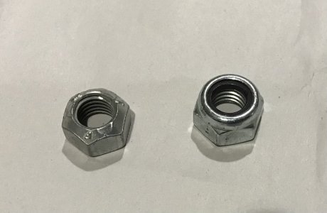
Castellated nut with a cotter pin would solve the problem nicely as well.
Yes, for me that's probably a better solution. No idea why I never dealt with this earlier. I guess it was just easy to live with it.
Castellated nut with a cotter pin would solve the problem nicely as well.
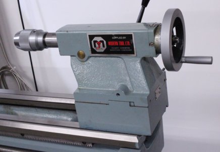
I have this problem on my tailstock too. The nut slowly backs off with use and sooner or later the lock handle won't lock anymore. Sometimes I don't notice it until the tailstock starts moving backward on me. It's never bothered me enough to fix it permanently. I just pull the tailstock off and give the nut a turn or two. It would be nice to be done with that forever with a mod like this.
Thank you!

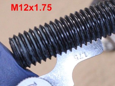
Thread locker
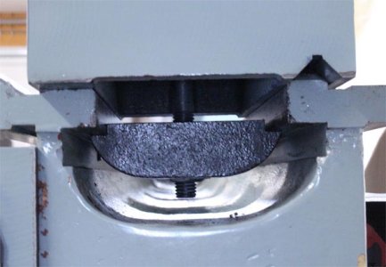
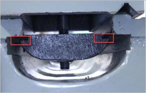
Hopefully you can see how the notches do not match the bed ways width wise. I might have enough meat in the plate to mill some material & attach better fitting guides. If not, I'll have to hunt down some steel plate & make a better one.
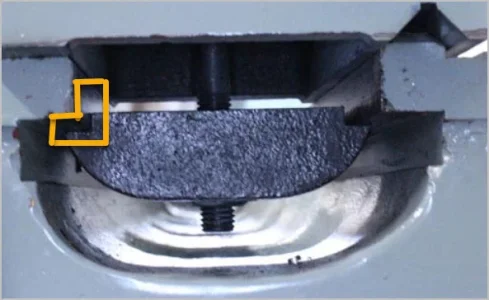
Kind of hard to show with the parallax perspective but I was thinking something like this. Seems to me I already dismissed the idea which is why it looks the same today LOL. For the same or lower effort I could mill something much better from new stock if I had an appropriate chunk of plate. I'm really not sure how they came up with this design. When the handle is loose & TS slides, the plate can rotate to extent the corners catch.
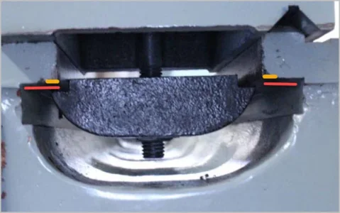
It might help as you say. But a new, corrected one would ideally solve all the issues simultaneously. Something like this.
I was sure I had a piece laying around specifically earmarked for this, but it must be hiding.
It might help as you say. But a new, corrected one would ideally solve all the issues simultaneously. Something like this.