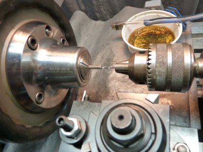
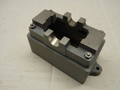
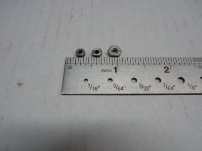
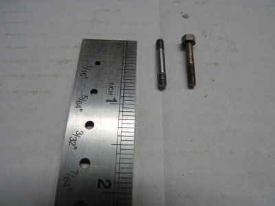
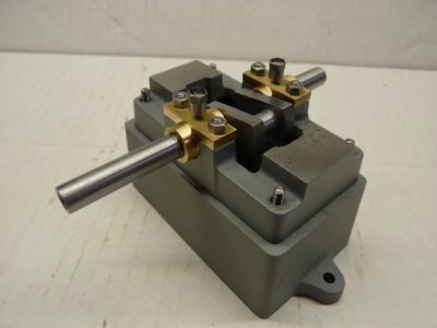
Hey,,,, wanna see my nuts? The ones I made for the engine,,,,, sheeeesh. Not a highly technical operation just took some time. Drill a hole, add some threads, part to approximate size, trim to size and repeat 28 more times. Pic 10v8 shows the BA nut, mine and the standard size 4-40 nut and the last pic shows the base and sole plate bolted together. The standard 4-40 nut would just barely sit on top of the stud but then there was no way to turn it and it was just way out of scale.
-
Scam Alert. Members are reminded to NOT send money to buy anything. Don't buy things remote and have it shipped - go get it yourself, pay in person, and take your equipment with you. Scammers have burned people on this forum. Urgency, secrecy, excuses, selling for friend, newish members, FUD, are RED FLAGS. A video conference call is not adequate assurance. Face to face interactions are required. Please report suspicions to the forum admins. Stay Safe - anyone can get scammed.
-
Several Regions have held meetups already, but others are being planned or are evaluating the interest. The Calgary Area Meetup is set for Saturday July 12th at 10am. The signup thread is here! Arbutus has also explored interest in a Fraser Valley meetup but it seems members either missed his thread or had other plans. Let him know if you are interested in a meetup later in the year by posting here! Slowpoke is trying to pull together an Ottawa area meetup later this summer. No date has been selected yet, so let him know if you are interested here! We are not aware of any other meetups being planned this year. If you are interested in doing something in your area, let everyone know and make it happen! Meetups are a great way to make new machining friends and get hands on help in your area. Don’t be shy, sign up and come, or plan your own meetup!
You are using an out of date browser. It may not display this or other websites correctly.
You should upgrade or use an alternative browser.
You should upgrade or use an alternative browser.
Stuart 10V Steam Engine Build
- Thread starter YotaBota
- Start date
CWelkie
Well-Known Member
One of those repetitive jobs that is satisfying when done - those nuts look much better than off-the-shelf hardware.
You've bumped into why many that do a lot of model building add BA taps/dies to the collection. Nothing else looks right (hex is too large, too thin, coarse thread relative to size, etc.). I figure that if I'm ordering in fasteners they can just as easily come from England as the US.
You've bumped into why many that do a lot of model building add BA taps/dies to the collection. Nothing else looks right (hex is too large, too thin, coarse thread relative to size, etc.). I figure that if I'm ordering in fasteners they can just as easily come from England as the US.
It's 3/16 hex, 303 stainless from McMaster Carr. I couldn't find it local at a price I was willing to pay so,,,,,, down south I went. I also bought .109 O1 drill rod to make the studs with.What material did you select?
The kit did come with the hardware but then I was having to buy BA taps, dies and wrenches for what could be a one off project. I already had taps, dies and wrenches for SAE sizes so decided to go that route. I did buy the 3/16 hex 5C collet just for this project and the ER40 collet chuck and collets I wanted anyway and will not be limited to this project.
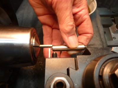
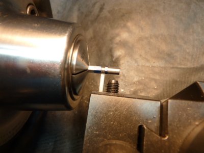
Once I get the engine running I'll probably see is anyone needs the BA hardware that came with the kit but not until the engine is done, still need some pieces for reference. The BA kit I have uses a lot of bolts but I like the look of studs. The pic shows the BA bolt beside the stud I made.
Size does matter when it comes to looking scale. 😉Nothing else looks right (hex is too large, too thin, coarse thread relative to size, etc.).
Attachments
I'm a bit confused...you didn't use BA hardware but off the shelf stuff was inappropriate size...what size and threads did you make? Maybe I need to dig out a 4-40 nut to grasp what size we are talking here.
The process is usually pick the closest NC thread and then make the hex the right size - either make the screws from scratch and machine the hex or use hex stock of the correct size. i.e. you're not use a 4-40 fastener, just 4-40 screw cutting tools. There used to be a few good vendors of model hex fasteners with appropriately sized heads, probably still are... but the few I dealt with, Coles and Power Model Supply are gone.
Years ago I wrote an article on making BA and ME ( NC threaded sized model engineering fasteners) nut drivers. Odd sized heads and wanting a very thin walled socket mean commercial nut drivers weren't available or very easy to use. Below is the table I developed by measuring BA and ME fasteners from model engineering vendors.
So, if you needed say a BA 7, you might make it a 3-48 with an .156" hex across the flats. Of course you can make the AF anything you think suits the scale and model, this just for ideas and what others have done.
for kicks, here's some shots of the drivers
Last edited:
Nice Mcgyver. I don't want to detract the build post, but if its not contravening the magazine, maybe you could do a little write-up post on how you made the sockets. I have a need for such tools. Unless you're going to tell us in a different magazine issue you show you how to first make a rotabroach LOL.
thank you! No rotabroach, handles are AL, shafts irrc are welding rod (the copper plated stuff) and the sockets mild steel case hardened. I'll get some photos together for a new thread. I thought it slightly relevant given the thread questions on hex size but don't what to further hijack it.
I don't have any metric tooling either.A 3mm size bolt and nut didn't look the right scale huh?
Absolutely relevant, you need the you need the correct size wrenches/sockets for the fasteners being used.I thought it slightly relevant given the thread questions on hex size but don't what to further hijack it.
As long as the picture is photo bombed with a steam flywheel and glass oiler all is good. lol
The nut drivers are a thing of beauty. I'd be interested in a build of the nut drivers as well, how are the handles and sockets attached to the shafts?
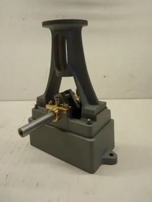
What is the piece in front of the flywheel?
Shafts on the nut drivers are welding rod? I don't follow. And I second YotaBota's build questions.thank you! No rotabroach, handles are AL, shafts irrc are welding rod (the copper plated stuff) and the sockets mild steel case hardened. I'll get some photos together for a new thread. I thought it slightly relevant given the thread questions on hex size but don't what to further hijack it.
DPittman
Ultra Member
Oh that makes sense. However usable hss metric taps and dies can be bought for cheap as opposed to the crazy BA stuff.I don't have any metric tooling either
I see my plans call for a 5/16x26 tpi tap for the piston rod gland. It appears that is a REALLY odd tap/pitch combo. What's your plan for that?
CWelkie
Well-Known Member
Mcgyver - thanks for the reminder of the article! I've no idea how that didn't get on my list of "shop tools to build" but have dug out the issue. Excellent article with lots of useful background information - in your usual style!
Got a full set of dies turned to "across points" dimensions this morning so am on the way ...
Got a full set of dies turned to "across points" dimensions this morning so am on the way ...
I'm just going to convert all the goofy sizes to what I have that's close, 5/16-24 etc.I see my plans call for a 5/16x26 tpi tap for the piston rod gland. It appears that is a REALLY odd tap/pitch combo. What's your plan for that?
historicalarms
Ultra Member
Attention to detail on the small stuff on how the OEM looked can sure add to the satisfaction of a build. I have two civil war cannon reproductions that imitate a time when all nuts & bolt heads were square so I built a bunch of them to suit for both projects but i also built a 1870's era revolving rifle model that I cheaped out on, took the easy route and used available modern hex stuff...I notice the difference every time I look at them.
In my case the square nuts and bolts for that matter, were easy to build....cut some washers off a 1" across the flats steel bar & drill & tap
In my case the square nuts and bolts for that matter, were easy to build....cut some washers off a 1" across the flats steel bar & drill & tap
😛1870's era revolving rifle model
Tom O
Ultra Member
That looks like a weighted governor for speed control.What is the piece in front of the flywheel?
Time for an update, the build is going more or less to plan and is following along the lines of all the build videos on youtube.
I've got the bottom end together, I turned the crank using a jig from a Blondehacks video:
The jig was adjusted to fit the throw and diameter of the shaft and worked well. I filled the web with JBweld to keep it from collapsing while between centers. I should've taken a few more pictures but got caught up in the moment of doing the job. The picture shows the JBweld in place and I'm turning the right side of the shaft to diameter. After this I used the Blondehacks jig and turned the rod journal.
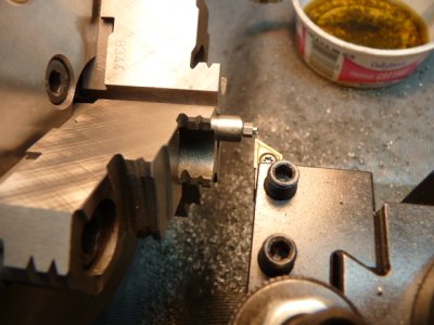
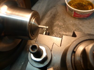
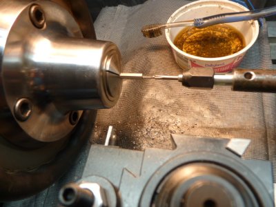
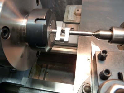
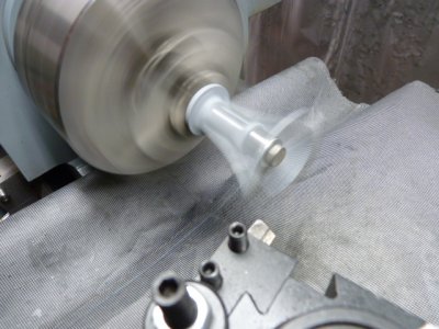
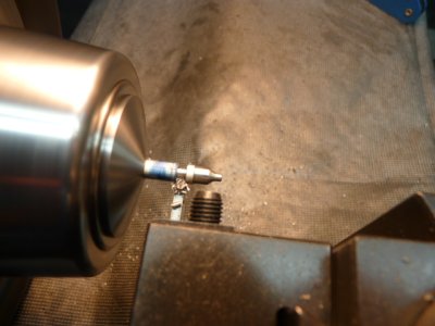
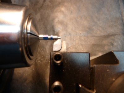
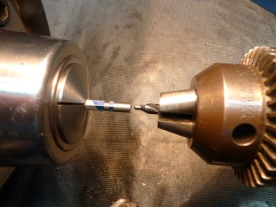
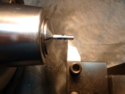
After the crank was done and the bearings turned to size the test fits came out good. I was going to use the drill to break in the crank/bearings but didn't want to have to baby sit with the oil can while it was turning so I turned oilcups ala Joe Pie, except I used a die for the threads vice single pointing on the lathe,
I used the 3/16 ss hex stock that also made the nuts. The pics show the making of the cups, it's tiny work but all went really well and they work/look good.
I've also got the standard started, again got caught up in doing the job and not enough pictures. I'm pleased with how it's gone so far, it's not a 5 cylinder radial but my skills aren't to level yet either.🙂
I've got the bottom end together, I turned the crank using a jig from a Blondehacks video:
After the crank was done and the bearings turned to size the test fits came out good. I was going to use the drill to break in the crank/bearings but didn't want to have to baby sit with the oil can while it was turning so I turned oilcups ala Joe Pie, except I used a die for the threads vice single pointing on the lathe,
I've also got the standard started, again got caught up in doing the job and not enough pictures. I'm pleased with how it's gone so far, it's not a 5 cylinder radial but my skills aren't to level yet either.🙂
Attachments
-
 Crankshaft.JPG38.3 KB · Views: 20
 -
 P1010846.JPG59.1 KB · Views: 23
 -
 Crank2.JPG26 KB · Views: 27
 -
 Oilcup6.JPG40.9 KB · Views: 22
 -
 Oilcup5.JPG35.5 KB · Views: 17
 -
 Oilcup4.JPG30.4 KB · Views: 17
 -
 Oilcup3.JPG44.5 KB · Views: 15
 -
 Oilcup2.JPG32.4 KB · Views: 17
 -
 Oilcup1.JPG36.6 KB · Views: 19
 -
 P1010882.webp13 KB · Views: 22