Follow along with the video below to see how to install our site as a web app on your home screen.
Note: This feature may not be available in some browsers.
Scam Alert. Members are reminded to NOT send money to buy anything. Don't buy things remote and have it shipped - go get it yourself, pay in person, and take your equipment with you. Scammers have burned people on this forum. Urgency, secrecy, excuses, selling for friend, newish members, FUD, are RED FLAGS. A video conference call is not adequate assurance. Face to face interactions are required. Please report suspicions to the forum admins. Stay Safe - anyone can get scammed.
Several Regions have held meetups already, but others are being planned or are evaluating the interest.
The Calgary Area Meetup is set for Saturday July 12th at 10am. The signup thread is
here!
Arbutus has also explored interest in a Fraser Valley meetup but it seems members either missed his thread or had other plans. Let him know if you are interested in a meetup later in the year by posting here!
Slowpoke is trying to pull together an Ottawa area meetup later this summer. No date has been selected yet, so let him know if you are interested here!
We are not aware of any other meetups being planned this year. If you are interested in doing something in your area, let everyone know and make it happen! Meetups are a great way to make new machining friends and get hands on help in your area. Don’t be shy, sign up and come, or plan your own meetup!
Yes, the narrow part crimps on the conductor while the larger part crimps on the insulation. Mine never crimped properly on the insulation, it just kind of squashed the tabs on the insulation. My new crimper crimps on both. It is a single operation. There are a number of YouTube video tutorials that may help. Search for “crimp dupont connector”.
Maybe an ah-ha moment? One of the stumbling blocks mentioned is the ram doesn’t have a fixed relationship with the base. The extend and retract movement can be adjusted so the end points are not always a set distance from a reference point.
rotary encoder can detect rotation in relative terms, cheap Arduino ones are 1024 pulses per revolution, rotation direction is a function of the sequence of quadrature output.
Wait for pulses to start
define direction of movement
count pulses for a specific period
some math
wait for pulses to stop and change direction
repeat & average for x number of seconds
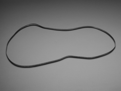
I picture a toothed belt, three rollers, and a tensioning device. Something like the photo, but with the belt coming off the lower left hand roller extending to the left, rather than the right as in the photo.
a 20-tooth pulley is about 15mm in diameter for a 2mm pitch belt, with 1000 pulses per rev the resolution is probably pretty good.
Timing belts are a fantastic way to transfer rotational motion (from a stepper motor) into linear motion (along a rail) and these GT2 belts are excellent for the task. They have a special ...
www.adafruit.com
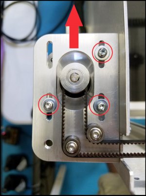
Attach the roller assembly to the machine base, anchor the belt ends to the extremes of the ram.
As long as the belt and roller orientation covers the full possible movement of the ram then all you’re dealing with is relative movement rather than absolute start stop points.
With some math & programming this could give you fpm as well as stroke length
@whydontu I'm pretty sure my concept is solid. I'm going to ping the US sensor off the back of the ram and calculate fwd/rev velocity. The problem is that this sensor is giving me grief....
Sonic transducer trying to hit a pin-point in open air repeatedly and reliably? Please excuse my potential ignorance here; but don't you actually just want to measure the radial velocity of the final drive wheel?
I guess GETTING to that drive wheel may be difficult (depending on the machine!) In a shaper (such as the fictional one here) the RPM of the Slider-crank disk should be proportional to the stroke speed?
I feel that changing over to a simple optical RPM sensor or a magnetic hall-effect would yield significantly better readings, and be less prone to environment noise (plus ever new result can be added to a rolling average to "tend toward" accurate values). (but I could well be wrong here!)
Do you have spikes in the data read from your ultrasonic sensor, like an HCSR04? Noise can be efficiently removed by simple median filter. Arduino code is provided.
Do you have spikes in the data read from your ultrasonic sensor, like an HCSR04? Noise can be efficiently removed by simple median filter. Arduino code is provided.
Do you have spikes in the data read from your ultrasonic sensor, like an HCSR04? Noise can be efficiently removed by simple median filter. Arduino code is provided.
That was a very good read. As I followed along with the description, I was also building the math in my head to define the velocity from the drive gear system. It was not what I expected before I started, but none-the-less quite doable.
However, as I finished the article, the author concluded the article with the math! So all my thinking was for nothing! I hate it when that happens!
I also concluded that the math was not necessary anyway. In the case of your shaper, it's way easier to just measure the ram movement directly and calculate velocity from the position in the Arduino almost exactly the same way that you would calculate rpm from a rotating part. The only differences between the two applications is that the shaper movement is linear so you need two sensors and you also need the code to distinguish between fwd and backward strokes.
I agree with @justindavidow . I think the US sensor approach is overly complicated. Frankly, so is the math approach. My instincts tell me that this job could even be done with proximity switches. But to be safe, two magnetic or hall effect proximity sensors located such that they can be used to measure the position of the ram and thereby calculate the average velocity is all that is required. If you make a bracket to hold the two sensors and glue two magnets onto the ram you are off to the races and can pull together the appropriate code.
I picture a bracket that looks like a DRO Scale mounted on the back side of the base and magnets or timing teeth mounted on the ram adjacent to the base. That way, the wires don't need to move.
For this application, optical sensors might be even better. In that case, I'd use two adjacent plates on each half (one on the ram and one on the base) with a hole in the ram plate.
But there are dozens of ways to skin this cat and US sensors will work too. It is just my personal opinion that proximity sensors are more robust, simpler to use, and less prone to interference.
One other comment may or may not have already been covered. Since the ram is a reciprocating device with slightly different forward VS reverse velocity, you need to distinguish between fwrd and reverse direction. With dual sensors located in the middle of the stroke, that is easy. Each sensor will fire twice and then the other sensor will fire twice and so forth and so on. So, the code should be setup to start counting time beats on the second pulse from the rear sensor and stop counting time beats on the first pulse on the forward sensor.
Regardless of how you do it, it is a nifty cool project. And thanks for helping me learn more about how a shaper works! I wish I lived closer.
The reason why I spoke about calibration is that the process lets you determine how frequently bad data is coming from the sensor and the potential effect of ignoring extraneous data as shown in that demonstration.
If your sensor returns bad data too frequently then ignoring blocks of data may make your calculated result imprecise. This is similar to why some industrial robotics and medical equipment must run on real time operating systems.
I agree with this. It's another reason that I favour a simpler more robust sensor system. A real time based OS or non-OS system (as I know them) isn't really practical with an Arduino or one or two sensors. It might get close with the system that @whydontu proposed or maybe with a rotary encoder.
But still, I prefer kiss. Therefore I'm now leaning more toward the light based IR sensor system. I'd bet (but have not checked) that they can be had in very precise versions over the counter. But if not, some attention to shielding from ambient light and shuttering for precision would make such a system plenty effective enough even over a very short distance for this application.
If I were doing it, I'd put two sender receiver pairs into opposite sides of a piece of rectangular aluminium (or plastic) attached to the base and an internal slider screen with narrow vertical slots in it that moves with the ram. The width of the slots would set the precision. A little calibration would be required to determine the appropriate correction factor for the Arduino. It would be a pretty bullet proof system that would as close to real-time as needed for great results on a machine of this type. Best of all, it could easily display feet per minute or whatever scale is desirable for the operation.
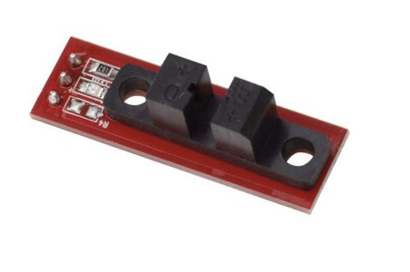
An optical end stop like this will work as a very accurate sensor. It wouldn’t directly give you direction, but if you assume the slowest is the cutting stroke then you could calculate fpm.
An optical end stop like this will work as a very accurate sensor. It wouldn’t directly give you direction, but if you assume the slowest is the cutting stroke then you could calculate fpm.
The end stop is a combination of an led and detector. When something opaque goes in the slot between them it is breaks the light beam. These are often used on 3d printers as an end stop.
I agree with this. It's another reason that I favour a simpler more robust sensor system. A real time based OS or non-OS system (as I know them) isn't really practical with an Arduino or one or two sensors. It might get close with the system that @whydontu proposed or maybe with a rotary encoder.
But still, I prefer kiss. Therefore I'm now leaning more toward the light based IR sensor system. I'd bet (but have not checked) that they can be had in very precise versions over the counter. But if not, some attention to shielding from ambient light and shuttering for precision would make such a system plenty effective enough even over a very short distance for this application.
If I were doing it, I'd put two sender receiver pairs into opposite sides of a piece of rectangular aluminium (or plastic) attached to the base and an internal slider screen with narrow vertical slots in it that moves with the ram. The width of the slots would set the precision. A little calibration would be required to determine the appropriate correction factor for the Arduino. It would be a pretty bullet proof system that would as close to real-time as needed for great results on a machine of this type. Best of all, it could easily display feet per minute or whatever scale is desirable for the operation.
Considering that it is easy to make a chart with the length of the cut on the X axis, and the speed of the cut on the why axis and then plot a line that will give you all the surface fpm possibilities of the shaper based on just one calculation it becomes hard to justify overly complex solutions that rely of twitchy sensors and more complex code.
See link at end of this post for a good video explanation of how the above chart is made and the best practice sensing methodology based on Arduino controller and the maths I am referring to below.
Programming and Hardware
Start with a sound tachometer sketch. Most sketches take about a second to calculate and display data because they elect to count the pulses in a set timeframe and then use that to calculate the resultant RPM which is the same as our strokes per minute here. In fact we want to sense the bull gear rpms to derive spm.
This is the tachometer sketch I prefer because instead the sketch measures only the time between pulses and then calculates the result. This requires only a single revolution of the bull gear.
Then your sketch should require the entry of the total stroke length in your Arduino sketch. This value is the sum of the length of the workpiece plus the small distances before and after the cutter engages the work.
It is my understanding that this value is easily obtained in the set-up of the shaper when preparing to cut the piece and trying to ascertain this from a sensor is less than ideal. I just don't know why you'd not want to enter this manually. Maybe I dont understand shapers well enough?I'm old but not that old where I got to work with a shaper.
If electing the manual entry you will need an LCD shield and keypad combination BUT again this is also well established code with standard libraries so you don't need to write anything new here either.
The same for having the Arduino sketch only count every complete revolution of the bull gear as your data. This is easy task for the Arduino with little to no chance of dropping a count. Hall Effect sensor and magnet only required.
Then you'd only need to write the calculation portion of the sketch. You could use simplified and inaccurate method or the more accurate but to Arduino neither task is difficult to perform very quickly and accurately.
The simple calculation most often employed is:
V = L x 2 x N,
where L = the total length of the forward stroke
2 is the multiplier to account for the backstroke,
and N is the number of strokes per minute.
The above is not the most accurate calculation however because the backstroke is much faster than the forward stroke due to the linkages on the bull gear.
The forward stroke accounts for about 2/3rd of the gear revolution, while the back stroke is about 1/3. Any calculation seeking to provide accuracy should account for this. BUT you don't need a hardware solution like an ultrasonic sensor. You just need maths.
So in 1 minute of operation there will be 40 seconds of forward stroke, and 20 of back stroke. Lets ignore the backstroke since it is meaningless to the result and we use a 40 second denominator for our calculation instead of using length x 2.
The calculation then becomes:
L x 60 x spm / divided by 40 = the mm per minute cutting speed
Where L is the total length of the stroke the user enters
60 is the number of seconds in a minute
spm (strokes per minute) is the calculated rpm output.
40 is the number of seconds in a minute that the shaper is taking the forward stroke.
With the Arduino running you'd only need to adjust your stroke speed until your output displayed hit your target millimeters per minute cutting speed.
Now if I am incorrect in my assumption that you can't easily ascertain the length of stroke during the set-up with a simple measuring device please let me know.
Personally for simple matters like this I prefer a chart.
I took what I have so far to the shaper and recorded 77 peak FPM in the fwd stroke and 146 peak FPM in the rev stroke. In my first post, I had predicted an average of 54 FPM.
I wish you'd have shown your work in that first post because I get a different result. I'll assume the methodology to derive the 52 forward strokes per minute is correct because it was likely from direct observation with a stopwatch.
6.25 inches/stroke x 52 strokes/min = 325 inches per minute
325 inches/min divided by 12 inches/ft = 27.08 feet/minute
6 inches is almost precisely 0.5 feet so you should have been able to see that the result should have been approx. 26 FPM.
Concerning your results at the shaper, the number of forward and reverse strokes MUST be equal. The travel on the forward stroke is LONGER than the reverse stroke based on the configuration of the bull gear linkages.
EDIT: I made a mistake I will correct here.
Ergo IF you calculate the results for both strokes the reverse FPM will be approximately twice the forward speed, due to the shorter stroke length.
If you were not getting such numbers you'd have a fundamental error somewhere in your calculations, program or hardware
Just a reminder the only one you should be using is the forward stroke as this gives you the ipm you need, factoring in the reverse changes this value. Using the reverse value in the equation is for calculating the working time which is dependent on both, better is to use a full cycle count & time for that.