• Scam Alert. Members are reminded to NOT send money to buy anything. Don't buy things remote and have it shipped - go get it yourself, pay in person, and take your equipment with you. Scammers have burned people on this forum. Urgency, secrecy, excuses, selling for friend, newish members, FUD, are RED FLAGS. A video conference call is not adequate assurance. Face to face interactions are required. Please report suspicions to the forum admins. Stay Safe - anyone can get scammed.

Someone check my math please.... Arduino Shaper Ram FPM Sensor

deleted_user

Super User
@TorontoBuilder check these out....


Thanks for the links. I'll read them shortly.

Have a look at these for my current lathe project:
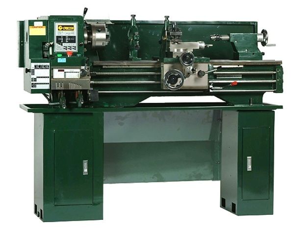
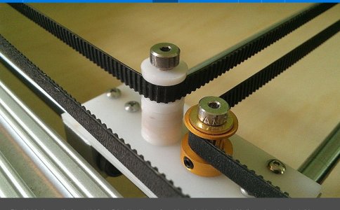
and

https://www.thingiverse.com/thing:5178575

I just can't leave it alone. I'm just sitting watching my 3d printer print a new front panel for my control box because I decided to add forward and reverse jog buttons. Why? Well I ordered what I thought were latching switches and I got momentary switches. So I couldn't let them go to waste.
 

whydontu

I Tried, It Broke
Premium Member
What's the difference? Looks like the same thing to me.
I have a few crimpers, the trick seems to be being very fiddly about the length of the stripped wire and making sure the connector is wedged properly in the crimping die. I’ll take some photos of my technique. It’s not 100% success rate, but is acceptable.

My experience with the IR sensors is they’re quite sensitive to ambient light. Without a shroud, my tach would stop working in the afternoon when my shop window lit up the shop.

No slur intended, as my coding skills are about equal to my singing skills, but I always look at other peoples code to figure out better ways to do things. The theremin I have is sold by these guys:


The code is open-source, I didn’t dig to deep but there’s probably some way to get the code and compare to yours.
 

YYCHM

(Craig)
Premium Member
No slur intended, as my coding skills are about equal to my singing skills, but I always look at other peoples code to figure out better ways to do things.

Yup, I keep looking for alternate implementations. Probably found about 6 so far, but they are all pretty much the same.

I might need a better ultrasonic sensor. The problem with this one is that the duration it returns keeps changing some what even when sounding off a fixed object and the variation gets worse with distance. I don't know why this would be but it does.
 

deleted_user

Super User
Yup, I keep looking for alternate implementations. Probably found about 6 so far, but they are all pretty much the same.

I might need a better ultrasonic sensor. The problem with this one is that the duration it returns keeps changing some what even when sounding off a fixed object and the variation gets worse with distance. I don't know why this would be but it does.

It sounds like you may be suffering from electrical noise interference, especially in shop environment.

Have you tested the sensor and micro-controller in a different space away from devices that may be emitters of EMI?
 

YYCHM

(Craig)
Premium Member
It sounds like you may be suffering from electrical noise interference, especially in shop environment.

Have you tested the sensor and micro-controller in a different space away from devices that may be emitters of EMI?

Currently attached to my PC in the basement rumpus room, no EMI here. Haven't move it to the shop yet.
 

YYCHM

(Craig)
Premium Member
I have the same on as yours but could never get a good crimp. The dies in the one I linked to are different and work very well. My crimps now look like they’re supposed to.

Ok, the dies on this one have a distinct jog in them. Is that to be expected?
 

Johnwa

Ultra Member
Ok, the dies on this one have a distinct jog in them. Is that to be expected?
If it’s what I think you mean then yes. That is the part that crimps over the insulation. Both my crimper s are like that except that one works and other one doesn’t.
 

deleted_user

Super User
Nothing to calibrate.
when I did my first projects with an Arduino sensor kit I did some calibration work on most of my sensors to fine tune readings. You should do the same with your sensor. I was getting inaccurate measurements over 4 feet. The point is though that you methodically record and graph measurements and that helps you identify a correction factor or see if you are getting inconsistent results in just a specific distance range or all over the place. This helps identify if you have wiring or interference issues.


Susquatch

Ultra Member
Administrator
Moderator
Premium Member
@YYCHM - I know little to nothing about the mechanical geometry of your shaper. Can you simply turn the machine by hand to determine the fwd/rev time ratio the old fashioned way? A bad guess could skew your numbers significantly.

I like @whydontu 's idea of using an Arduino. Not just because you can find out the ratio and other parameters, but mostly because it can become a permanent fpm gauge. I've read through the post and wish I had seen it earlier to help with the early math. At this point, I'd just be confusing the matter. Instead, I'll only remind you that fpm is a velocity quantity which is the rate of change of distance with time.

You don't need to position the sensors at the ends of travel to determine it. In fact, that's probably a poor choice. The Arduino can handle measuring the time for any distance and it is plenty fast enough to discern almost any cutting speed that machine of yours can generate. Nonetheless, I would recommend an integer distance of say two or four inches in the middle of the stroke so that you can do the math in your head and know that the output number that the Arduino produces is correct. Calibration in the code or in the sensor spacing will be important.

That said, the sensors do not have to be on the ram. They can be anyplace where you know the geometry and the physical relationship between the parts. In fact, putting them on the rotating parts has the advantage that you can have just one rpm sensor and not have to worry about separating out the fwd/rev strokes.

If you need help with that math, I'll happily engage. I would enjoy looking at the geometry and learning a bit more about shapers. Just ask.
 

whydontu

I Tried, It Broke
Premium Member
Maybe an ah-ha moment? One of the stumbling blocks mentioned is the ram doesn’t have a fixed relationship with the base. The extend and retract movement can be adjusted so the end points are not always a set distance from a reference point.

Is there a sensor to target position that can cover all possible ranges of movement? then you measure A to B, measure B to A, do some math to calculate differences over time.

What about using an 18” or 24” iGaging scale for input?

or could be as simple as a rotary encoder being driven by a toothed belt, such as the ones used for crap 3d printers.

the Arduino programming is way beyond my skill set, but shouldn’t be that tricky for a real programmer


Attachments

  • A58447C2-9579-4D30-AF18-E59D349E2AE9.jpeg
    A58447C2-9579-4D30-AF18-E59D349E2AE9.jpeg
    640.6 KB · Views: 1
  • 1A358183-4871-4B95-88B1-F50D63D425A8.jpeg
    1A358183-4871-4B95-88B1-F50D63D425A8.jpeg
    1.4 MB · Views: 1
Last edited:

Chicken lights

Forum Pony Express Driver
Ok, the dies on this one have a distinct jog in them. Is that to be expected?
Do you have the end in backwards? The part you’re trying to crimp on. My crimpers are made by Grote and they’re fussy too.
I have the best luck starting the to close the tabs with a regular pair of pliers, then using the crimping tool to do the crimp.
 

YYCHM

(Craig)
Premium Member
Do you have the end in backwards? The part you’re trying to crimp on. My crimpers are made by Grote and they’re fussy too.
I have the best luck starting the to close the tabs with a regular pair of pliers, then using the crimping tool to do the crimp.

I don't think I'm putting the pins in backwards. I've looked at a few videos and sample instructions.
 

Susquatch

Ultra Member
Administrator
Moderator
Premium Member
Is there a sensor to target position that can cover all possible ranges of movement? then you measure A to B, measure B to A, do some math to calculate differences over time.

That's essentially the first idea I tried to explain - but poorly as usual...... Any distance during the main portion of the primary stroke will do.

Here you go, knock your socks off....

Awesome! Leave it with me!

I don't think I'm putting the pins in backwards. I've looked at a few videos and sample instructions.

I agree with @Chicken lights . Those crimpers work best if you close the tabs a bit first with needle nose pliers. But have a close look at your crimpers first. Some have a spot that acts like a staging crimp to setup the ears for the next operation. They are basically a two stage operation.
 

YYCHM

(Craig)
Premium Member
But have a close look at your crimpers first. Some have a spot that acts like a staging crimp to setup the ears for the next operation. They are basically a two stage operation.

CrimperJaws.JPG

Here is a shot of the crimper jaws Two stage? @Johnwa This is what I meant by a jog.
 

Johnwa

Ultra Member
View attachment 19615

Here is a shot of the crimper jaws Two stage? @Johnwa This is what I meant by a jog.
Yes, the narrow part crimps on the conductor while the larger part crimps on the insulation. Mine never crimped properly on the insulation, it just kind of squashed the tabs on the insulation. My new crimper crimps on both. It is a single operation. There are a number of YouTube video tutorials that may help. Search for “crimp dupont connector”.
 
Top