• Scam Alert. Members are reminded to NOT send money to buy anything. Don't buy things remote and have it shipped - go get it yourself, pay in person, and take your equipment with you. Scammers have burned people on this forum. Urgency, secrecy, excuses, selling for friend, newish members, FUD, are RED FLAGS. A video conference call is not adequate assurance. Face to face interactions are required. Please report suspicions to the forum admins. Stay Safe - anyone can get scammed.
  • Several Regions have held meetups already, but others are being planned or are evaluating the interest. The Ontario GTA West area meetup is planned for Saturday April 26th at Greasemonkeys shop in Aylmer Ontario. If you are interested and haven’t signed up yet, click here! Arbutus has also explored interest in a Fraser Valley meetup but it seems members either missed his thread or had other plans. Let him know if you are interested in a meetup later in the year by posting here! Slowpoke is trying to pull together an Ottawa area meetup later this summer. No date has been selected yet, so let him know if you are interested here! We are not aware of any other meetups being planned this year. If you are interested in doing something in your area, let everyone know and make it happen! Meetups are a great way to make new machining friends and get hands on help in your area. Don’t be shy, sign up and come, or plan your own meetup!

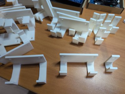
Tips/Techniques Show your shop related 3DP

Tips/Techniques
I did file the lead in ramp to get a smoother action. A very good design for my uses. Thank you Peter T!
Pierre

IMG_9992.jpeg
 
I did file the lead in ramp to get a smoother action.

Actually there really is no reason not to make a ramp on both sides, just mirror it. Then it wouldn't matter which way the lid went on. The thicker clasp on the lid is the only unique feature. I might make the thumbnail part a bit bigger. I was also thinking of something more like a circular groove on the inside corner to act like a flexure vs the sharp 90-deg corner. Details, details...
 
Details details... yes. I was inspired to give it a go. Trying for a hinged lid. No idea of those ears for the screws will work or just bust.
1746412032161.png1746412242603.png
printing now in red. about an hour for the lid and 90 minutes for the box.
We need a plug in for xenforo to let you view and spin the .stl files...
 
Fusion rendered image. I wish I could print this perfectly. This is with the rough powder coat appearance.
 

Attachments

  • 100mm box study v5.png
    100mm box study v5.png
    6.3 MB · Views: 8
That's pretty cool you can make those. For a couple tool sets I bought old empty snap on cases, hollowed out the innards and made them fit. I never would have thought of being able to make my own cases
 
@Janger & @PeterT

I like my stuff to fit without wasted spaces between things. Consider moving those hinges inside the box. A cone head screw could be mounted flat to the outside of the case. Put all your reinforcements inside so the only wasted space is for the hinge itself. A 3D printer should make that easy to do.

Inside hinges allow for boxes that can cuddle together without all that wasted space between them and behind them. An inside hinge also makes a propped lid (opens to say 120° or so) much easier to do.
 
I haven't seen those variable speed controls before, are they SB and what motor are you running ?
I'm running the original 1 hp, 2-speed, 3-phase motor powered and controlled by a Vevor 2.2kw VFD. I gutted the drum switch and wired it to the VFD low voltage inputs for forward and reverse. The speed control is just a 10k ohm potentiometer also wired to the VFD inputs and the tach is a $20 unit off eBay with a hall effect pickup. I printed the the tach housing and pot mount.
 
I'm running the original 1 hp, 2-speed, 3-phase motor powered and controlled by a Vevor 2.2kw VFD. I gutted the drum switch and wired it to the VFD low voltage inputs for forward and reverse. The speed control is just a 10k ohm potentiometer also wired to the VFD inputs and the tach is a $20 unit off eBay with a hall effect pickup. I printed the the tach housing and pot mount.
Nice, thanks.
 
You know those instrument battery covers with the slot? Yes, the slot made to no particular standardized width, each one is a bit different. Maybe they are based on Asian coins because Canuck coins aren't much better fit than stamped metal ones assuming one was included. I just 3DP'd as set in various incremental thicknesses. Hint, don't use a blade screwdriver, they are guaranteed to mangle the soft plastic.
 

Attachments

  • 20052501.jpg
    20052501.jpg
    30.7 KB · Views: 4
  • 20052502.jpg
    20052502.jpg
    41.2 KB · Views: 4
  • 20052504.jpg
    20052504.jpg
    79.3 KB · Views: 4
This is an example of something I've been doing more as of late. When you want to fit something with some degree of snugness but the printer tolerance and/or part tolerance can vary a bit so it becomes a trial & error repetition. Sometimes its easier to make the cavity match the actual part dimension, but add some kind of flexure slot so there is some give in the surrounding material.
 

Attachments

  • 20052506.jpg
    20052506.jpg
    20.8 KB · Views: 4
  • 20052508.jpg
    20052508.jpg
    30.1 KB · Views: 4
Back
Top