• Spring 2024 meetup in Calgary - date Saturday, April 20/2024. discussion Please RSVP Here to confirm and get your invitation and the location details. RSVP NOW so organizers can plan to get sufficient food etc. It's Tomorrow Saturday! you can still RSVP until I stop checking my phone tomorrow More info and agenda
  • We are having email/registration problems again. Diagnosis is underway. New users sorry if you are having trouble getting registered. We are exploring different options to get registered. Contact the forum via another member or on facebook if you're stuck. Update -> we think it is fixed. Let us know if not.
  • Spring meet up in Ontario, April 6/2024. NEW LOCATION See Post #31 Discussion AND THE NEW LOCATION

Rotary Table Questions

Susquatch

Ultra Member
Administrator
Moderator
Premium Member
Great story!

So it is no coincidence that components start to fail right after the warranty is up. Who would have guessed that?

Look at this fellow’s quest for a precision dividing head (it is a two part series). Alex is on a whole other level of precision…


Typical German Engineer....... I recognize his type in the mirror too......
 

Dabbler

ersatz engineer
@Susquatch , you might want to talk to @Johnwa about his spin indexer conversion. It might be easier, given your background. He built an electronic addition to get any number of divisions, and far less error prone than doing it manually! A work of art, really...
 

PeterT

Ultra Member
Premium Member
I was just going to suggest the same. The electronic systems I've seen installed on RT's are actually very slick. Enter any angle & it magically goes there. No plates, no sector arms, no notepad scribbles... Quite a few documented installations & kits. The electronics is above my pay grade but you seem to be familiar with this stuff.
 

Johnwa

Ultra Member
I've come across a few links (including John's mentioned above). Here is one of them

https://www.homemodelenginemachinist.com/threads/arduino-rotary-table-for-dummies.26744/

That is where I first found it. The original version in that thread had a couple of issues. I rewrote some of the code to address those issues. Another member of HMEM made some more changes including adding acceleration which allows for faster stepper speeds. I have a copy of his code but am still using my version.
 

Susquatch

Ultra Member
Administrator
Moderator
Premium Member
That is where I first found it. The original version in that thread had a couple of issues. I rewrote some of the code to address those issues. Another member of HMEM made some more changes including adding acceleration which allows for faster stepper speeds. I have a copy of his code but am still using my version.

I looked at your project briefly and made a comment there about your battery.

The project is very cool! I'll review it in more detail shortly.

One thing I have noticed in my short time on this forum. All you guys seem to spend more time making tools for your tools than making parts. I always thought I was the only one who did that......
 

Susquatch

Ultra Member
Administrator
Moderator
Premium Member
I was looking for index plate info and saw the post below on practical machinist. Its an old post about rotary tables so I didn't want to jump in. But it raises some questions. First off, I don't think it's correct but I can see how they got their numbers.

QUOTE FROM PRACTICAL MACHINIST
40:1 is 9 turns for 360°
60:1 is 6 turns
72:1 is 5 turns
90:1 is 4 turns

120:1 is 3 turns

I am told that mine is a 90:1 RT. I believe that those who told me that are correct. What I also know for certain is that my table turns 4 degrees for every full turn of the crank not 4 turns per 360. In my case, it takes 90 turns of the crank to turn the table 1 turn. So I think 90:1 is correct, but that is the crank to table ratio, not all those other terms that I see elsewhere including on this post. In my world all drive ratios are specified as input to output. I've never seen otherwise.

So, what's the real deal with this and why all the confusion out there? Am I missing something?
 

Dabbler

ersatz engineer
I don't know what the 'Practical Machinist' guy was thinking. I have 2 RTs and a B&S indexer.

-- I think that in an effort to make things simple, they made it waaay harder.

Einstein said: "Make thing as simple as possible, but no simpler"
 

PeterT

Ultra Member
Premium Member
Just a few additional observations.
As far as I have seen, there are no plates with 540 holes, so there are no plates with 1 minute resolution. Yet, the regular crank handle on my RT will resolve 1 minute - with near zero backlash! There is wayyyy more backlash and error using those plates........ So why are they so popular? Surely it can't be just the convenience!

Dividing plates are mostly a convenience to position the chuck/table/whatever 'output' to some target angular increment. For example if I need to cut a 27 tooth gear, I can:
1) mount the plate which has a 27 hole circle, crank (1 turn + 13 holes), cut the tooth, rinse & repeat.
2) turn the RT wheel the exact amount. So 360/27= 13.333333 degrees, so crank to 13-deg plus corresponding degree-minute-second graduation to 0.33333 remainder. Cut the tooth, then repeat that 26 more times without a math error or inadvertent division slip up.

On simple, nominal divisions it might be quicker to use the RT dial but that's because the graduation readily aligns. On more complex combinations, as long as you can count & stick it in the hole (LOL), it removes the math. So the fact that an interim hole division happens to works out to some very fine angular remainder (what you all resolution) is just a secondary artifact of the math, not really the purpose of the plate IMO. So the likely reason is there are no super high hole count plates is a) hard to fit that many holes on a small diameter plate b) equates to gears or splines that are so fine they are generally uncommon in most everyday mechanisms.

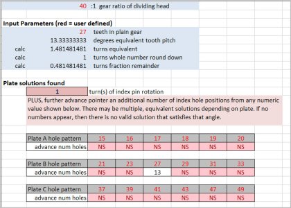
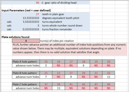
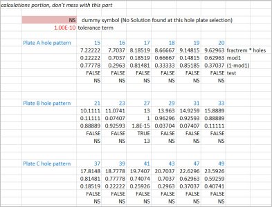
Been a long time since I looked at this stuff, but I wrote a spreadsheet where I can input the gear ratio & the desired tooth count (or angle which is related) & it spits out the plate/hole combination. There are tables on the internet but I wanted to figure it out. So a few things are evident. The gear ratio & plate must be known because they work in conjunction with one another. A 40:1 will have a different hole combination than a 90:1. And different plates may yield the same angle with different hole combinations. And some tooth count/angle combinations are not possible because non-evenly divisible. And I guess if you ever wanted to use a different worm/gear/plate combination, maybe there is a new & exciting gear tooth you could achieve! LOL

https://cdn.shopify.com/s/files/1/0424/4249/0019/files/Final_-_Combined.pdf?v=1623448375

Lastly, I think backlash is backlash whether you are using method 1 or 2. You must always advance in one direction. You can pause but you cannot overshoot & backup, otherwise backlash is introduced. If you go slightly past the target hole on a plate & then jiggle it in, that's technically a no-no. But no different than inadvertently going past the target dial increment & reverse creeping to the target.
 

Attachments

  • SNAG-2021-10-15 7.12.26 PM.jpg
    SNAG-2021-10-15 7.12.26 PM.jpg
    164.4 KB · Views: 10
  • SNAG-2021-10-15 7.31.21 PM.jpg
    SNAG-2021-10-15 7.31.21 PM.jpg
    164.5 KB · Views: 10
  • SNAG-2021-10-15 7.49.43 PM.jpg
    SNAG-2021-10-15 7.49.43 PM.jpg
    200.8 KB · Views: 10

Dabbler

ersatz engineer
@PeterT a very nice elegant little spreadsheet. It was what I was trying to say 'with math' you can find plate/tooth combinations to do what you need... Of course, I hadn't seen all the way to your solution - you are brilliant!
 

Susquatch

Ultra Member
Administrator
Moderator
Premium Member
Thanks guys. Sometimes I think I am going crazy. Things have to make sense to me but they often don't. The internet has become a crazy place with too much crap out there.

@Dabbler - Einstein was an amazing man. I wish I could have met him or even just sat and listened to him once. Yes, "make it as simple as possible, but no simpler......." a worthy goal indeed. But not one I am very good at. That said, I accept your point. It sits very comfortably in my mind. And no worries, I believe I did understand what you were trying to say.

@RobinHood - Perfect! I agree totally! I feel better now.

@PeterT - I've seen others on-line talk about spreadsheets to do this stuff and I've tried unsuccessfully to find one. Looking at your results tells me I don't need to find one. I'm very comfy with the math. Your first paragraph says it all nicely. It's just easier and less error prone to use the plate. The only quibble I have with that is the result of watching others use a plate in their videos. Almost all fail to account for backlash (just as you describe), and I've yet to watch anyone execute the simple process without screwing up in moving the arms or making the indexer fit the right hole correctly. What should have been simple and error free - simply wasn't.

I guess I'll have to try both approaches to see what I really prefer to do myself. Making the adapter to use my existing plates will be a labour of love so why not? Easy to write my own spreadsheet and create my own charts. Also easy to hand calculate a list of target settings.

Either way, it's easy to check the results too. It either ends up at 360 with the right number of increments or I screwed up and it doesn't........

Thanks guys.....
 

RobinHood

Ultra Member
Premium Member
Almost all fail to account for backlash (just as you describe), and I've yet to watch anyone execute the simple process without screwing up in moving the arms or making the indexer fit the right hole correctly. What should have been simple and error free - simply wasn't.

I hear you on that point.

Most dividing heads / RTs have the ability to en/disengage the worm from the worm wheel. The backlash can be “totally“ eliminated by snugging the two components tightly together. One gets away with this (unlike in other gear trains where you need a certain amount of clearance) because it is a very slow speed system. So, the “only“ source of backlash comes from overshooting the hole in the plate. Turning it back to engage the hole will cause the spindle to rotate backwards. On good quality DHs/RTs, the pin engaging the hole is tapered. It will find center.

Another thing to remember is that any error in positioning is reduced by the ratio of the worm to worm gear.

I tend to leave on the lock so it just drags a bit. Makes it very easy to find the center of the hole in the chosen direction.

Some sector arms also have a ramp. If you carefully position them, the pin can slide down the ramp and never miss the hole.

The above comments are only valid when either direct indexing or indirect indexing. Using differential dividing is a different animal as now there is a gear train involved (and they need a tiny bit of backlash). Dragging the brake helps a lot in the case. If you overshoot, no problems: just turn the crank a good turn back and then forwards and hopefully this time don’t miss the hole.

When I made the 127T gear for the SM1340 metric to imperial conversion, it worked very well, albeit it took a long time to make.
 

Dabbler

ersatz engineer
@Susquatch I wanted to grow up to be like Einstein when I was little.

@RobinHood As the sector is usually used, the ramp is on the wrong side of the backlash, but - as you say, is easily corrected.

Using a RT with even several thou out on any single tooth will never make a difference on any gear, especially on a 127 tooth (or larger) gear.
 

Dabbler

ersatz engineer
based on your calculator, the only way to get to 127 on a RT is with direct indexing on a 127 plate.
 

PeterT

Ultra Member
Premium Member
I haven't looked at my xls in years now but a couple of spot checks looks like same result as Brent online program.

I was wondering about the 127 tooth myself, That works out to 2.834645669... degrees. @RobinHood did you accomplish this by directly dialing in each angular setting, or?
I know exactly why 127 is a sought after gear, so it comes up often. Discussed here.
https://www.hobby-machinist.com/threads/127-hole-plate-for-b-s-bs0.21342/page-2

another post
https://bbs.homeshopmachinist.net/forum/general/10991-gear-cutting#post248476

I think the conclusion is with either so called common 40:1 or 90:1 ratio, there is no plate/hole combination <127 holes that satisfies exact solution? Maybe its related to prime numbers or some such concept?

My spreadsheet has my own index plates hole count pre-loaded, but I can input any arbitrary hole count in to see if a solution is possible. My next step was to enter a target gear & have it solve for the closest solution & leave it to you to decide if its close enough. But where's the fun in that when I could just draw it in CAD with hole spacing accurate to 20 decimal places & export to CNC guy who hopefully can drill it to 3 decimal places LOL
 

Dabbler

ersatz engineer
Exactly. If one had a 127 plate made, then set the sector arms for 90 holes, there you have it.
 

RobinHood

Ultra Member
Premium Member
I think the conclusion is with either so called common 40:1 or 90:1 ratio, there is no plate/hole combination <127 holes that satisfies exact solution? Maybe its related to prime numbers or some such concept?

Yes, because 127 is a prime number.

I have an “Universal” dividing head (B & S #2 type). It has external change gears to allow “differential division”. I my case, the formula called for 11 holes movement on a 33 hole plate; 24T gear on the input shaft, 56T on the spindle shaft, and 40T & 44T between them to make up the space and cause the reference shaft to rotate in the correct orientation.

Edit: my universal dividing head is a B & S #2 - which is the universal dividing head. B & S only made three types: the 0, 1 and 2.
 
Last edited:
Top