• Scam Alert. Members are reminded to NOT send money to buy anything. Don't buy things remote and have it shipped - go get it yourself, pay in person, and take your equipment with you. Scammers have burned people on this forum. Urgency, secrecy, excuses, selling for friend, newish members, FUD, are RED FLAGS. A video conference call is not adequate assurance. Face to face interactions are required. Please report suspicions to the forum admins. Stay Safe - anyone can get scammed.

Rotary Table Questions

Exactly. If one had a 127 plate made, then set the sector arms for 90 holes, there you have it.
Attached. What else can I help you with this morning? LOL

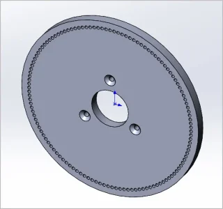
This probably illustrates another thing. I sketched this at 6" OD, 127 pin holes x 0.100" diameter just as a visual. Its getting rather tight spacing. And there could be a limitation as to how large the plate diameters can be depending on the device & installation. But this illustrates why you don't see plates available with super high hole count in order to hit minute-second angles.

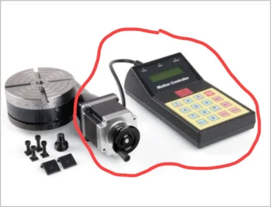
I wish there was a plug-n-play electric add-on accessory for RTs. I can solder but I'm lost in the programming. If the stepper motor could be counted on to reliably increment to this kind of resolution, it would be so much easier to type in a number & watch it rotate. That's even better than a DRO display which just passively displays where you are at. Well somehow we got along with plates for the past hundred years or more. I think the reason the electronics stuff is mostly in the domain of creative hobbyists is because CNC makes quick work of this stuff. Either the mill head moves or its a 4-axis, either way digitally driven.
 

Attachments

  • SNAG-2021-10-16 10.18.34 AM.webp
    SNAG-2021-10-16 10.18.34 AM.webp
    19.2 KB · Views: 3
100% agree with your observation regarding CNC, or the use of affordable electronics in the small shop. Oh, and the problem with lots of holes on a small diameter plate…

If the universal DH had not come with my mill, that is exactly what I would have done. But since I have it, and all the change gears, it was just waiting for me to use it. Worked exceptionally well.
 
Yes, because 127 is a prime number.
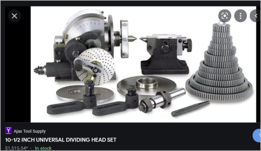
I have an “Universal” dividing head (B & S #3 type). It has external change gears to allow “differential division”. I my case, the formula called for 11 holes movement on a 33 hole plate; 24T gear on the input shaft, 56T on the spindle shaft, and 40T & 44T between them to make up the space and cause the reference shaft to rotate in the correct orientation.

Ah! I get it now, thanks. Yes, change gears would add more versatility than worm/wheel style.
 
So in “indirect” dividing, the plate is fixed to the DH and only the crank handle moves the appropriate number of holes.

In “differential“ dividing, the plate is on a geared shaft. It rotates in either the same direction as the crank or in the opposite direction to make up the “difference” that the crank moves the spindle either too far or not enough for each division. The “difference” being a function of (and controlled by) the change gears feeding back to the hole plate.

It basically solves fractions using gear ratios - very ingenious.
 

Attachments

  • SNAG-2021-10-16 11.27.42 AM.jpg
    SNAG-2021-10-16 11.27.42 AM.jpg
    58.2 KB · Views: 2
It “should” be easy enough to couple a stepper motor to the handle of the RT and then use a computer to drive the motor for the required angle for each gear tooth or hole? Yes?/No?
 
@PeterT that is what the Universal Head looks like with differential gears. Like mine and @RobinHood - we both have the same unit, but mine was made in Poland. I've never taken the gears out of the cosmoline! (shame, shame!)
 
It “should” be easy enough to couple a stepper motor to the handle of the RT and then use a computer to drive the motor for the required angle for each gear tooth or hole? Yes?/No?

yes - but. Many of the add on libraries for arduino and raspberry pi have decent motion control, but as @Johnwa found out, one can do a lot better by custom programming.
 
It “should” be easy enough to couple a stepper motor to the handle of the RT and then use a computer to drive the motor for the required angle for each gear tooth or hole? Yes?/No?
The indexer that I made will also work with a RT. There is a menu to change the “gear” ratio to match the ratio of the RT.
 
As has been said, 127 is a prime number. IMHO the indivisability of a prime number is no big deal to the end result. Using extreme decimal places only to demonstrate, one finds that:

360/127 = 2.834645669 degrees
= 2 degrees 50.07874014 minutes
= 2 degrees 50 minutes 4.7244084 seconds

4.7244084 seconds of arc is just 0.001312336 degrees which is just 0.000022905 inches at 1" radius
Half that at 1/2" radius
Twice that at 2" radius
In fact, the radius must be 43" (diameter is 86 inches) before the seconds of arc become one thou.

In other words, it is meaningless for all intents and purposes. Just set your table to the degrees and rounded minutes and go.

N RT setting
0 0 degrees
1 2 degrees 50 minutes
2 5 degrees 40 minutes
3 8 degrees 30 minutes
4 11 degrees 20 minutes
5 14 degrees 10 minutes
6 17 degrees even

Etc all the way to

126 357 degrees 10 minutes
127 360 degrees even
(same as 0)

The formula is:

(360/127) x tooth number = degrees
Subtract whole degrees
Multiply remainder x 60 = minutes
Round minutes to nearest whole number
Dial in the degrees and rounded minutes
Cut the gear tooth.

Consider for a moment the precision of the plate hole. Does anyone here really believe that any of those holes on that 4" plate is within 0.000004 of an inch from the correct location? Then there are all the other errors too. Just lining up that hole pin and stressing the mechanism being a huge one.......

IMHO, rounded minutes of angle using a plain old calculator, a programmable calculator, or a spreadsheet are no doubt more accurate than the plate despite its magical prime number membership.

That all said, if I had a plate w 127 holes in it, I'd prolly use it. As much as I believe the actual error using a plate would be greater than rounded minutes, they are probably still inconsequential to the quality of the gear being cut.

Just my two cents for whatever they are worth to others here.
 
@Johnwa : did you post the build on here? Any plans? Etc.

I love the idea too. Just got a few Arduino's. They are still in their static proof bags. But I can hear one of them screaming about wanting to turn my RT crank for me! It will have to round off the minutes first though...... LOL!
 
@Susquatch I followed the build described in HMEM by BMac2 @PeterT gave a link to that in post #45. A number of us took stabs at resolving issues with the Arduino code. I believe kquiggle’s version is the last one.
 
I hear you on that point.

Most dividing heads / RTs have the ability to en/disengage the worm from the worm wheel. The backlash can be “totally“ eliminated by snugging the two components tightly together. One gets away with this (unlike in other gear trains where you need a certain amount of clearance) because it is a very slow speed system. So, the “only“ source of backlash comes from overshooting the hole in the plate. Turning it back to engage the hole will cause the spindle to rotate backwards. On good quality DHs/RTs, the pin engaging the hole is tapered. It will find center.

Another thing to remember is that any error in positioning is reduced by the ratio of the worm to worm gear.

I tend to leave on the lock so it just drags a bit. Makes it very easy to find the center of the hole in the chosen direction.

Some sector arms also have a ramp. If you carefully position them, the pin can slide down the ramp and never miss the hole.

The above comments are only valid when either direct indexing or indirect indexing. Using differential dividing is a different animal as now there is a gear train involved (and they need a tiny bit of backlash). Dragging the brake helps a lot in the case. If you overshoot, no problems: just turn the crank a good turn back and then forwards and hopefully this time don’t miss the hole.

When I made the 127T gear for the SM1340 metric to imperial conversion, it worked very well, albeit it took a long time to make.

I believe I understand your points and I agree to the extent that others are able to do what you do.

But I'm not sure they can.

I spent a fair bit of time looking at the dividing plate mechanism on my universal dividing head. (yes, I know it isn't the same). In particular I was interested in understanding it's limitations. How well does it minimize stress related errors. How well does the point truly engage the hole. How often does it have to be wiggled into position. How does the user have to adjust it to minimize these errors. I ended up concluding that I would never be able to set the angular position of my RT nearly as well with a divider plate as I could just using the crank manually with backlash in mind.

Perhaps your unit is better than mine. But it's difficult for me to see how a sliding pointer on a spring loaded drum on a relatively weak arm can really hold to a minute of angle.

Perhaps a test is in order..... But I don't have a clue right off hand how to do that!

In any event, I suspect that debating which is better is largely just an interesting academic exercise.

The most important thing that both you and I do agree on is that it's important not to delude ourselves about how much accuracy is really needed to cut an awesome gear.

I think there is an old saying for this. "Never let the perfect be the enemy of the good."

I have no real fear of using either approach to make a great gear.
 
@Susquatch I followed the build described in HMEM by BMac2 @PeterT gave a link to that in post #45. A number of us took stabs at resolving issues with the Arduino code. I believe kquiggle’s version is the last one.

Yes, I noticed that.

I wish I could do just this and nothing else. I'd get it done yet this week. But that isn't the reality of my life right now.

Nonetheless, I do want to do this. I may or may not use kquiggle's latest version to do so. I've always enjoyed customizing such things and in particular I'm looking forward to mixing Arduino code with machine language code for the atmega chip. That is a big step, but as they say,..... We will see.
 
One of the chief advantages of the index plate method is that once you have the sector arms set then you really have to bugger up to get a misplaced tooth. You don’t have to count holes or match your dials up with a long list of numbers, just move the plunger and sector arms.

I don’t know if using dials or an index plate is more precise. Fortunately any error with either one is divided by the table ratio.
 
@Susquatch the thing I liked the best about BMac‘s write up was that he had his wife wire one up based on his instructions. That was enough of a kick in the butt to get me to build mine.
 
Back
Top