• Spring 2024 meetup in Calgary - tentative date Saturday, April 20/2024. Other regions are also discussing meet ups. If you want one in your area get going on organizing it! discussion
  • We are having email/registration problems again. Diagnosis is underway. New users sorry if you are having trouble getting registered. We are exploring different options to get registered. Contact the forum via another member or on facebook if you're stuck. Update -> we think it is fixed. Let us know if not.
  • Spring meet up in Ontario, April 6/2024. NEW LOCATION See Post #31 Discussion NEW LOCATION

Radial engine build

PeterT

Ultra Member
Premium Member
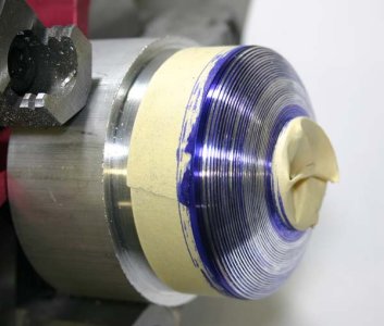
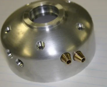
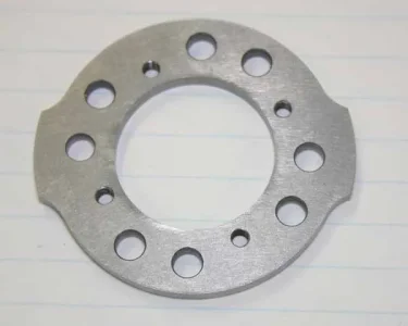
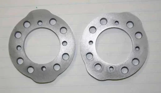
Finally! The cam plates are done. Made from A2 tool steel. Never worked with this stuff before. Its quite tough but light cuts & patience finished up OK. These need to be hardened so I've made contact with a local knife maker guy who has the appropriate equipment. Because the thinness & non-symmetrical shape & array of holes etc. I decided to try A (air) over O (oil) quenching tool steel. I figure with the work that went into them I just didn't want to add extra risk of 'potato chip' distortion if it were to hit a liquid quenched. So after heating in a stainless bag they get 'air' quenched but sandwiched between 2 aluminum plates. Then tempering to whatever temp to target hardness.

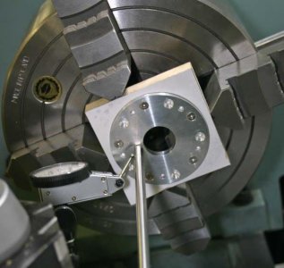
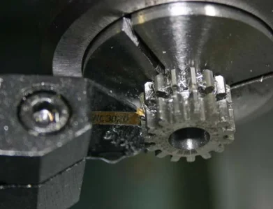
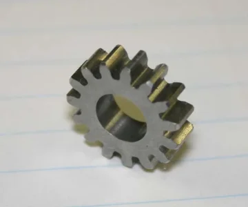
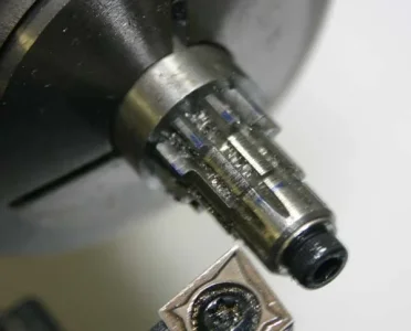
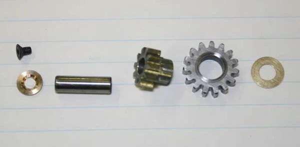
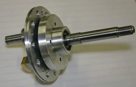
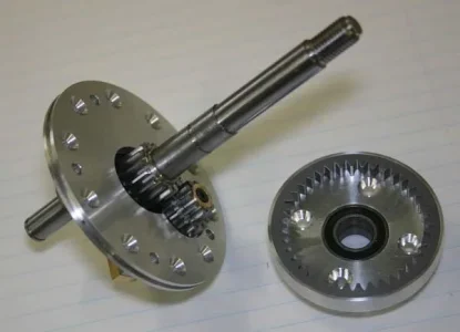
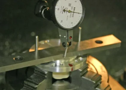
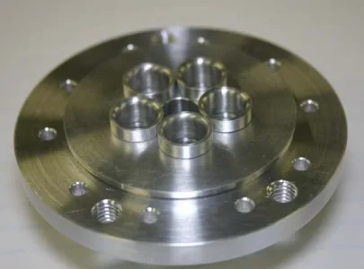
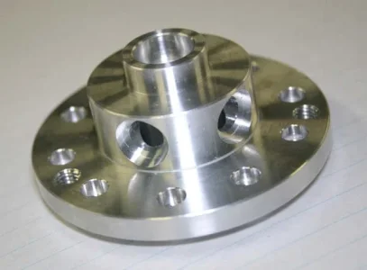
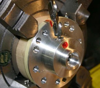
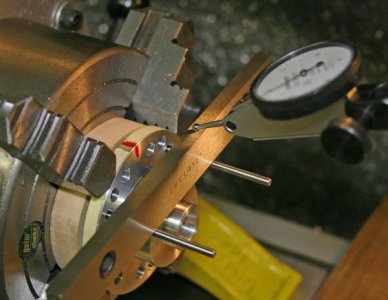
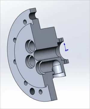
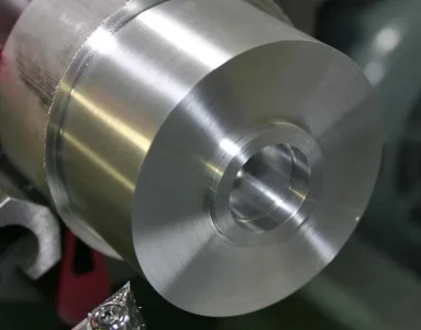
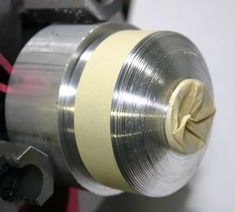
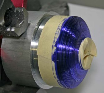
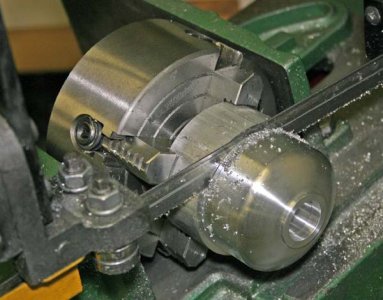
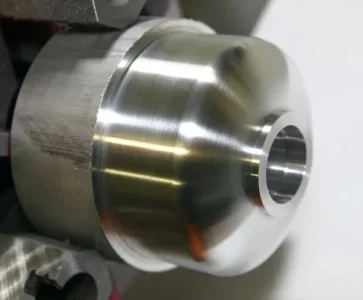
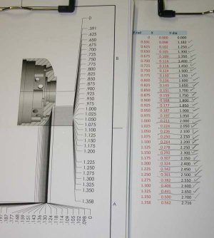
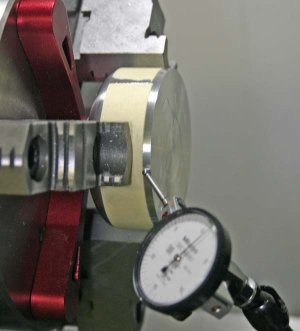
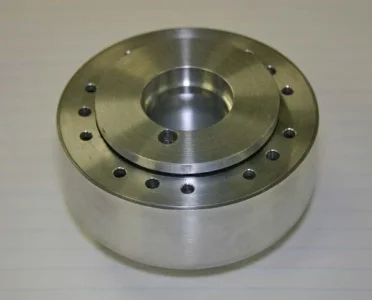
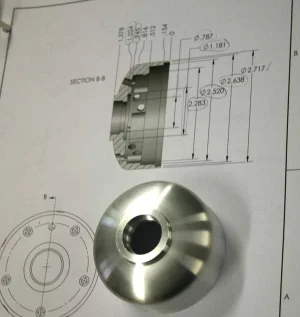
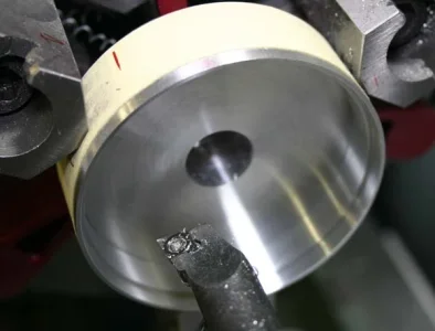
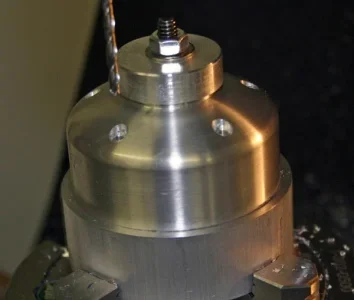
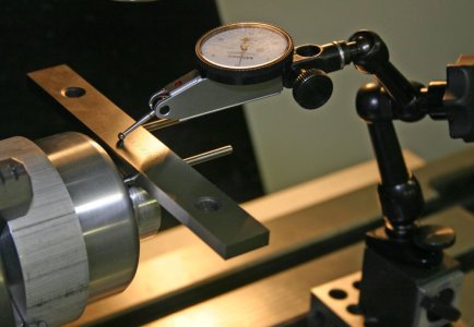
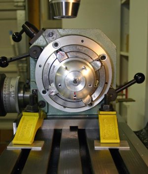
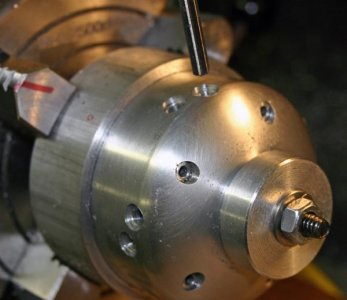
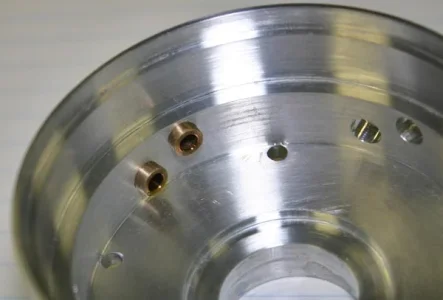
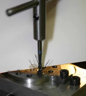
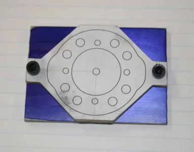
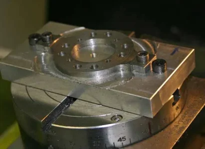
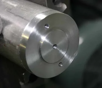
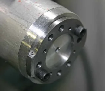
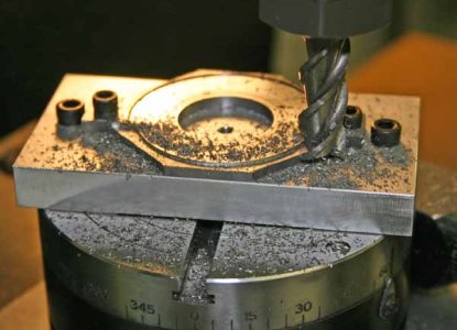
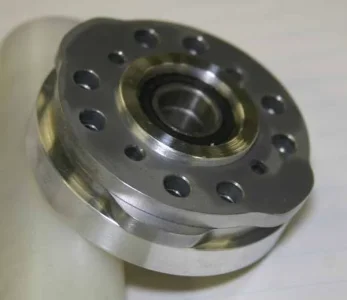
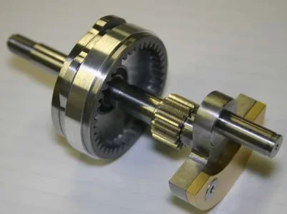
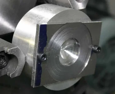
One lathe fixture was to hold the blank for center hole boring & reducing thickness to 3.5mm (metric plans) from IMP stock. Then part transferred to another mini rotary table fixture to mill the 2 (valve closed) radius arcs, then screw holes & lightening holes. One cam is intake, the other is exhaust, so the relative phasing once stacked comes about by orientation of M3 tap & clearance holes. So lots of RT angle positions to remember. Then I cut the ears off & utilized the holes to secure it to another lathe fixture for the OD (valve open) turning. Then some careful Dremel grinding to make a nice transition up the ramp of the lobe & polishing with rubberized abrasive.

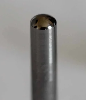
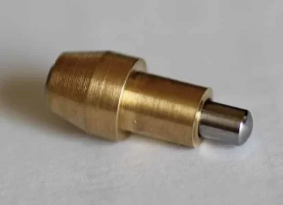
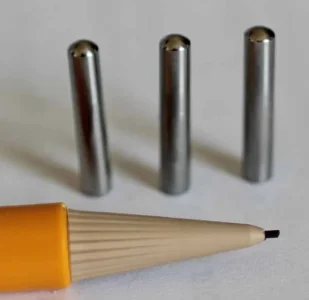
I think I'm going to make these next so I can send them out together. Basically I want the followers to be a couple Rockwell points under the cam plates so the wear is on the easier to replace part. They are made from 4mm O1 round stock. They have a hemi-ball shape on the end that runs along these cam profiles. The other end is an internal (ball mill divot) here the rocker pushrods locates into.
 

Attachments

  • IMG_6948_edited-1.jpg
    IMG_6948_edited-1.jpg
    38.2 KB · Views: 15
  • IMG_6941_edited-1.jpg
    IMG_6941_edited-1.jpg
    39.9 KB · Views: 16
  • IMG_6958_edited-1.jpg
    IMG_6958_edited-1.jpg
    41.8 KB · Views: 15
  • IMG_6960_edited-1.jpg
    IMG_6960_edited-1.jpg
    33.5 KB · Views: 14
  • IMG_6962_edited-1.jpg
    IMG_6962_edited-1.jpg
    38.1 KB · Views: 14
  • IMG_6963_edited-1.jpg
    IMG_6963_edited-1.jpg
    34.5 KB · Views: 14
  • IMG_6965_edited-1.jpg
    IMG_6965_edited-1.jpg
    51.3 KB · Views: 14
  • IMG_6970_edited-1.jpg
    IMG_6970_edited-1.jpg
    33.5 KB · Views: 14
  • IMG_6971_edited-1.jpg
    IMG_6971_edited-1.jpg
    36.5 KB · Views: 19
  • IMG_6972_edited-1.jpg
    IMG_6972_edited-1.jpg
    37.5 KB · Views: 19
  • IMG_6947_edited-1.jpg
    IMG_6947_edited-1.jpg
    38.4 KB · Views: 19

PeterT

Ultra Member
Premium Member
Made a good start on the tappets. Material is O1 tool steel. Only about .0015" has to come off stock diameter but pretty much impossible to turn this small amount on something so skinny, long & somewhat tough material. But it needs to be 0.0005" clearance relative to 3mm reamed hole in tappet guide. This was a PITA. I messed around with lapping fixtures, but in the end it was net faster to just work it down with various grits of paper & measuring often.

The end that runs against the cam profile plate has a dome profile, basically a point contact. The profile itself is not super critical because its essentially a point contact, but I wanted all 10 (+ 2 spares) to be the same. So I held in 5C collet chuck & used Radii turning tool to form the basic shape. Then I chucked the rod in my Dremel & to remove tooling marks, progressively finer WD paper & finally lapping compound embedded in felt.

What remains now is turn to each to final length. Then cut a dome recess on the other side for the pushrod using 2mm ball end mill, polishing etc. Monotonous but relativity straightforward. With the cams & tappets complete, I can send the parts away for & prescribe hardening. Cross my fingers nothing warps too bad given the time invested. I'm really not sure what to expect there so wish me luck.

The actual tappet guides are made of bronze, I caught that detail after I made mockup from brass. But I think I'll hold off making those until the parts come back from hardening.
 

Attachments

  • IMG_0996_edited-1.jpg
    IMG_0996_edited-1.jpg
    28 KB · Views: 9
  • IMG_0997_edited-1.jpg
    IMG_0997_edited-1.jpg
    27.4 KB · Views: 12
  • IMG_1000_edited-1.jpg
    IMG_1000_edited-1.jpg
    32.8 KB · Views: 11

DPittman

Ultra Member
Premium Member
Made a good start on the tappets. Material is O1 tool steel. Only about .0015" has to come off stock diameter but pretty much impossible to turn this small amount on something so skinny, long & somewhat tough material. But it needs to be 0.0005" clearance relative to 3mm reamed hole in tappet guide. This was a PITA. I messed around with lapping fixtures, but in the end it was net faster to just work it down with various grits of paper & measuring often.

The end that runs against the cam profile plate has a dome profile, basically a point contact. The profile itself is not super critical because its essentially a point contact, but I wanted all 10 (+ 2 spares) to be the same. So I held in 5C collet chuck & used Radii turning tool to form the basic shape. Then I chucked the rod in my Dremel & to remove tooling marks, progressively finer WD paper & finally lapping compound embedded in felt.

What remains now is turn to each to final length. Then cut a dome recess on the other side for the pushrod using 2mm ball end mill, polishing etc. Monotonous but relativity straightforward. With the cams & tappets complete, I can send the parts away for & prescribe hardening. Cross my fingers nothing warps too bad given the time invested. I'm really not sure what to expect there so wish me luck.

The actual tappet guides are made of bronze, I caught that detail after I made mockup from brass. But I think I'll hold off making those until the parts come back from hardening.
Wow. Just simply wow.
 

johnnielsen

John (Makonjohn)
Premium Member
I have used skiving with success on small items like that. Glad the abrasive route worked so well for you.
 

johnnielsen

John (Makonjohn)
Premium Member
https://www.productionmachining.com/articles/the-forgotten-art-of-skiving

https://www.sommatool.com/manuscripts/is-13a.asp

http://www.practicalmachinist.com/v...l-skiving-tool-283635/?highlight=Skiving+tool

It takes some playing around but once you get the angles right it is amazing. The way I remember it was like taking a long cylinder cutting pass on wood lathe where the tool has a flat straight 90 degree nose that is held at a 15 to 30 degree angle from the vertical. The back side has a relief angle on the back to ensure only the front edge touches the work piece. Picture a manual type wood chisel with an 80 degree bevel instead of a 25 degree bevel.
 

PeterT

Ultra Member
Premium Member
Progress on the front gear plate & planetary drive. The metric spur gears are commercial (steel) but each had to be modified to make the idler cluster.
The 5mm idler shaft is O1 which I hardened myself with torch. I discovered it is sufficiently hard because there is a fiddly 90-deg partial countersink for M2.5 flathead bolt & it was a teeny bit shallow. I had a bugger of a time deepening it with HSS so had to grind on it a bit. All good though, everything seems to run smooth.
 

Attachments

  • IMG_7068_edited-1.jpg
    IMG_7068_edited-1.jpg
    56.2 KB · Views: 18
  • IMG_7078_edited-1.jpg
    IMG_7078_edited-1.jpg
    49.4 KB · Views: 18
  • IMG_7079_edited-1.jpg
    IMG_7079_edited-1.jpg
    34.1 KB · Views: 18
  • IMG_7083_edited-1.jpg
    IMG_7083_edited-1.jpg
    45.2 KB · Views: 18
  • IMG_7088_edited-1.jpg
    IMG_7088_edited-1.jpg
    39.6 KB · Views: 18
  • IMG_7090_edited-1.jpg
    IMG_7090_edited-1.jpg
    34.6 KB · Views: 18
  • IMG_7094_edited-1.jpg
    IMG_7094_edited-1.jpg
    29.1 KB · Views: 17

PeterT

Ultra Member
Premium Member
Here is the rear intake manifold / engine mount plate progress. Fuel enters from the rear through the center hole via a (commercially purchased ) RC carburetor into the crankcase chamber. Because the methanol fuel has some oil added, this internal detour helps lubricate the connecting rod assembly. In a 'real' radial, this aspect of lubrication is handled by an oil pump, squirter tubes & recycle. From the crankcase, the inlet charge exits back out through one of the 5 radial ports up its respective induction tube into the head. You can see some nozzle-ettes that eventually get Loctited into place. I still have to turn some bosses which go into respective counterbores on the outside manifold section. They have internal o-ring grooves t seal the tube, so I will have to muck around with what kind of induction tubing I will use & pre-establish fits etc because these bosses also become permanently attached. Mostly this was lathe turning & rotary table work in lay-down & up-right positions. Thee is only one way it goes on the crankcase, so several alignments to keep in the noodle.
 

Attachments

  • IMG_7135_edited-1.jpg
    IMG_7135_edited-1.jpg
    46.1 KB · Views: 12
  • IMG_7137_edited-1.jpg
    IMG_7137_edited-1.jpg
    45.5 KB · Views: 12
  • IMG_7145_edited-1.jpg
    IMG_7145_edited-1.jpg
    41.8 KB · Views: 12
  • IMG_7147_edited-1.jpg
    IMG_7147_edited-1.jpg
    55.7 KB · Views: 12
  • IMG_7153_edited-1.jpg
    IMG_7153_edited-1.jpg
    42.3 KB · Views: 12
  • IMG_7149_edited-1.jpg
    IMG_7149_edited-1.jpg
    66.7 KB · Views: 12
Last edited:

PeterT

Ultra Member
Premium Member
The 5 ports are first pilot drilled then bored with a ball end mill to depth. Then do this at 90-deg in the other plane & results a smooth-ish gas passage corner.
 

Attachments

  • IMG_7149_edited-1.jpg
    IMG_7149_edited-1.jpg
    66.7 KB · Views: 6
  • SNAG-6-2-2018 0002.jpg
    SNAG-6-2-2018 0002.jpg
    25 KB · Views: 6

PeterT

Ultra Member
Premium Member
Here is the nose case in progress. I still have to drill the 5 front attachment bolts & 10 radial tappet counterbores. Most of it was conventional turning but a few dimensions had to be trial & error fitted, namely the front bearing ID & lip ID which fits against an O-ring seal on the gear plate. I originally thought i could use the Radii cutter for the front profiling but the case is too large for the Radii swing. So I worked out a table of XY intercepts, blued the stair steps & filed & sanded until no more blue showing.

The original plans had some complicated internal pocket relief milling features which I stared at for a long time, wondering why he did things this particular way. I didn't like how the bolt holes were landed through material half open which I was sure was going to cause me drill deflection grief. The pocket milling leaves a bit more meat for the tappet guides to reside in but maybe not enough to justify the setup work & my endmill looked a bit short for the job. So.............. I 'simplified' it a bit & therefore running the risk of making this part all again if I discover something I hadn't considered properly. TBC. This nose case houses the planetary gears & & cam plates, so it is half filled with oil so these parts get splashy happy in the lubrication.
 

Attachments

  • IMG_7154_edited-1.jpg
    IMG_7154_edited-1.jpg
    41.8 KB · Views: 9
  • IMG_7155_edited-1.jpg
    IMG_7155_edited-1.jpg
    52.4 KB · Views: 9
  • IMG_7157_edited-1.jpg
    IMG_7157_edited-1.jpg
    55.4 KB · Views: 9
  • IMG_7158_edited-1.jpg
    IMG_7158_edited-1.jpg
    56.8 KB · Views: 9
  • IMG_7159_edited-1.jpg
    IMG_7159_edited-1.jpg
    69.7 KB · Views: 9
  • IMG_7161_edited-1.jpg
    IMG_7161_edited-1.jpg
    42.3 KB · Views: 9
  • IMG_7163_edited-1.jpg
    IMG_7163_edited-1.jpg
    67.2 KB · Views: 9
Last edited:

PeterT

Ultra Member
Premium Member
Backside turning.
 

Attachments

  • IMG_7164_edited-1.jpg
    IMG_7164_edited-1.jpg
    50.4 KB · Views: 10
  • IMG_7169_edited-1.jpg
    IMG_7169_edited-1.jpg
    45.7 KB · Views: 9
  • IMG_7176_edited-1.jpg
    IMG_7176_edited-1.jpg
    37.8 KB · Views: 11
  • IMG_7173_edited-1.jpg
    IMG_7173_edited-1.jpg
    49.3 KB · Views: 10
  • IMG_7172_edited-1.jpg
    IMG_7172_edited-1.jpg
    88.5 KB · Views: 10
  • IMG_7177_edited-1.jpg
    IMG_7177_edited-1.jpg
    42 KB · Views: 9

PeterT

Ultra Member
Premium Member
Nose case mounting holes & radial tappet holes operation completed. I made a fixture which fits the ID of the nose case & retained with a threaded stud & washer disc. That then gets dialed in & clamped in 4-jaw chuck which is turn is mounted to RT. The fixture lip needs to be quite snug fit but based on a dicey prior experience, I was more concerned about getting them apart because its aluminum on aluminum & lots of close fitting contact area. So I used a light smear of ant-seize compound. That for sure helped.

Its looking like my modification will work out. Relief, I really didn't want to make this part again. One more tapped hole to make on the front face for oil fill plug & that's it.
 

Attachments

  • IMG_7180_edited-1.jpg
    IMG_7180_edited-1.jpg
    43.8 KB · Views: 9
  • IMG_7204_edited-1.jpg
    IMG_7204_edited-1.jpg
    47.5 KB · Views: 9
  • IMG_7207_edited-1.jpg
    IMG_7207_edited-1.jpg
    88.3 KB · Views: 9
  • IMG_7209_edited-1.jpg
    IMG_7209_edited-1.jpg
    79.9 KB · Views: 9
  • IMG_7211_edited-1.jpg
    IMG_7211_edited-1.jpg
    52.3 KB · Views: 11
  • IMG_7214_edited-1.jpg
    IMG_7214_edited-1.jpg
    39.6 KB · Views: 11
  • IMG_7215_edited-1.jpg
    IMG_7215_edited-1.jpg
    43.9 KB · Views: 11

Janger

(John)
Administrator
Vendor
We’re going to have to have a party at Peters to celebrate this odyssey. When can we see it run?
 

PeterT

Ultra Member
Premium Member
HaHa. My goal was to get this 'middle engine stuff' done by end of summer (crankshaft drive train, crankcase, manifold...). I think I'm mostly on track (and breathing a sigh of relief). Then comes '5 times everything' mode, meaning 5 assemblies of cylinders/liners/heads/pistons/valves... Maybe this time next year if its a productive winter? I'd like to get out to the flying field now because our summers are so dang short. So I'll pick away at some smaller tasks over the next few months.
 

PeterT

Ultra Member
Premium Member
Only radio control models. Been doing it since I was a kid. Started on typical sport models, then pattern (aerobatics) for quite a while, then pylon racing, then a brief stint with heli's (the dark side). Now I'm messing around with 4m span electric sailplanes. The motors are just to get to altitude, then its basically a thermal event. I've kind of done RC events in 10 year chunks for whatever reason, so I'll probably stick with this for a while. The reflexes aren't quite what they used to be LOL.
 
Top