• Scam Alert. Members are reminded to NOT send money to buy anything. Don't buy things remote and have it shipped - go get it yourself, pay in person, and take your equipment with you. Scammers have burned people on this forum. Urgency, secrecy, excuses, selling for friend, newish members, FUD, are RED FLAGS. A video conference call is not adequate assurance. Face to face interactions are required. Please report suspicions to the forum admins. Stay Safe - anyone can get scammed.

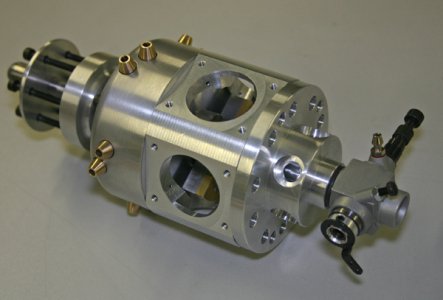
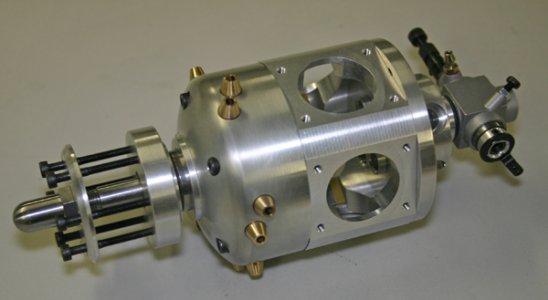
Radial engine build

Only radio control models. Been doing it since I was a kid. Started on typical sport models, then pattern (aerobatics) for quite a while, then pylon racing, then a brief stint with heli's (the dark side). Now I'm messing around with 4m span electric sailplanes. The motors are just to get to altitude, then its basically a thermal event. I've kind of done RC events in 10 year chunks for whatever reason, so I'll probably stick with this for a while. The reflexes aren't quite what they used to be LOL.
Sounds fun. One of my childhood friends built RC planes and eventually a helicopter. It always intrigue me and I loved the engines. I had cast off Cox 0.49 engines that I would make snow sleds and boats for. Neat hobby RC stuff. I am now nearing completion of a 2 seater ultralight airplane I built (kit form) . Just some bigger than your sailplanes! It's taken forever to get this far (reasons not related to actual building) and now it's pretty high on the bucket list to actually get it flying. I fear the bucket might go flying first!
Don
 
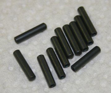
My hardened tool steel goodies arrived back from the nice folks at Canadian Knifemaker out of Sundre. https://www.knifemaker.ca/
Big shout out to them. I couldn't be happier because they are not in the business of miniature radial engines but obviously know how to heat treat metal. I dropped them in the mail with some verbiage, followed up with a phone call. A short while later they arrived back by post at very reasonable price. This resource has opened up new avenues for me (and saved me looking for a $ oven hopefully many years).

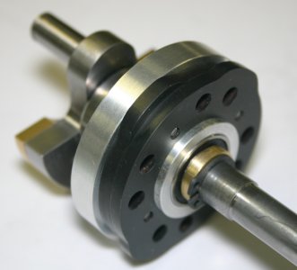
The cam plates are A2 (air quench) tool steel chosen for minimal distortion in quench. I asked for 55 hardness. So they go into sealed foil bags with a oxygen consumable, raised to temperature & soak time. Then get quenched at room temp by clamping between aluminum plates. Then back in the oven for tempering at specific reduced temperature/time to achieve the desired hardness. They came out this silky black color which can be removed by hard scuffing but I'll probably leave it for no other reason than monitor any wear from the tappets. The big relief was no measurable distortion in the plate in the potatoe chip orientation. The bore shrunk about .0015" which was totally acceptable. It fin teh ring gear cup no problem. YAY.

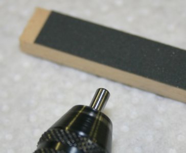
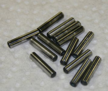
The tappets are O1 (oil quench) tool steel. I could have gone A2 too excep they are 3mm nominal stock & O1 was all I could find. Anyway, same story except these are target 50 hardness to wear preferentially. They get oil quenched & I was actually more concerned they might bow & be problematic in the sliding fit of bronze guides. Here I spun them in the Dremel & 1200 paper to remove the black & buff them to final sliding fit. I have no way of verifying the hardness numbers were achieved but I have to trust the process. And its 100% better than I could have achieved with my Neanderthal fire stick & can of oil.
 

Attachments

  • IMG_7220_edited-1.jpg
    IMG_7220_edited-1.jpg
    33.5 KB · Views: 10
  • IMG_7222_edited-1.jpg
    IMG_7222_edited-1.jpg
    20.9 KB · Views: 10
  • IMG_7224_edited-1.jpg
    IMG_7224_edited-1.jpg
    44.5 KB · Views: 11
  • IMG_7292_edited-1.jpg
    IMG_7292_edited-1.jpg
    28.9 KB · Views: 11
Last edited:
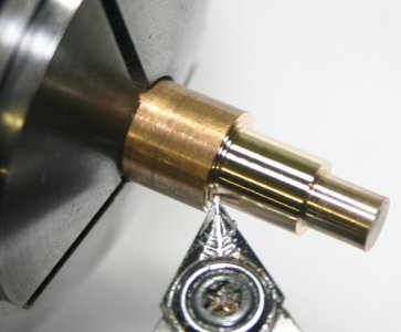
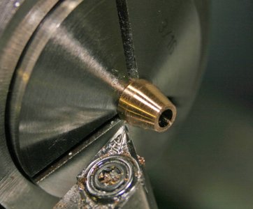
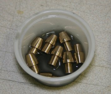
These are the bronze tappet guides. They are pretty straightforward, drilled & reamed & tapered. But its amazing when parts get small scale like this even a tiny burr from chamfering or reaming can be felt in the fit. So I used a brass lap with 1000G compound which made them all consistent. Then the compound has to be removed so consecutive cleaning baths of thinners & Q-tips.

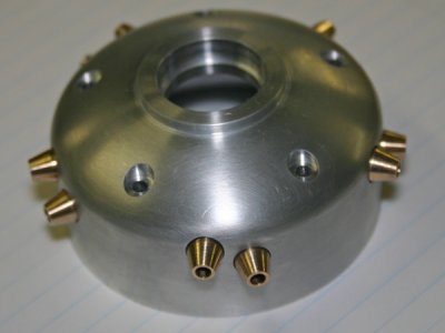
For machining I find a sharp un-coated insert tool works best (same one I prefer on aluminum). Drilling small diameters isnt a big deal but larger drills definitely need edge dubbing or the material can grab mess things up. Another big relief is my nose case modification from the plans seems to have worked out, at least AFAIK. The guides eventually get installed with permanent Loctite.
 

Attachments

  • IMG_7229_edited-1.jpg
    IMG_7229_edited-1.jpg
    32.8 KB · Views: 10
  • IMG_7230_edited-1.jpg
    IMG_7230_edited-1.jpg
    41.3 KB · Views: 10
  • IMG_7232_edited-1.jpg
    IMG_7232_edited-1.jpg
    41.1 KB · Views: 10
  • IMG_7233_edited-1.jpg
    IMG_7233_edited-1.jpg
    22.1 KB · Views: 12
That is some fine work! Well done. I am very intrigued. I am hoping to do some scale stem engine build at some point. However being a very new metal worker, I will need to hone my skills somewhat before I tackle an actual engine.
Thanks for sharing
 
Well, I feel fall weather coming so figured its time to migrate back to the shop & pick up on the radial build. I left the project this spring with some specific problems to solve on the head.

1) I needed to sort out how to make the induction & exhaust tubes, their end flares & coupling nuts into the head. I think that aspect got dealt with here.
https://canadianhobbymetalworkers.com/threads/brake-line-flare.1314/#post-13421

2) Making the intake/exhaust ports has been challenging. They enter the head at a funky compound angle, they must intercept the valve cage at a precise spot, the holes are counter-bored & threaded to accept the tubing nuts and the thread depth is stupidly shallow. I thought I could accomplish this with careful setup in the mill & using modified taps but that turned out to be problematic. Its very hard for a tap to engage properly when the tap is only cutting on half its body for 6 or more initial threads until the whole body is cutting. So I tweaked the head diameter to net me slightly more material to work with and I've come up with a new lathe based jig that has the angle & offset incorporated. I will attempt single point threading the head in the lathe. More to come on that front

3) I had to finalize the valve cage assembly into the hemi shaped combustion chamber. Judging by engine forums, valve seal is the singlemost trouble maker for scale engines. A minor leak stops you dead in your tracks despite the usual blueing & lapping methods. Its one of those things that just doesn't 'scale' from the full size engines. So best results are when the seat itself is cut teeny, like 0.010-0.015" across the 45-deg vs say 2-3X that if it was scaled. The theory is less seat is better, the valve settles in quicker, finds a happy home & kind of wears itself into a seal if everything goes right. So I had to depart from the plans & redesign the cage a bit. But I also achieved better conformance of the valve bridging flat across the hemi bowl. They can't protrude much before getting dangerously close to the piston. They also cant be recessed too much because it makes nooks & crannies for crud to build up & the head volume is very sensitive to compression ratio changes. Anyways, I think I have a method I can replicate. Here is the bronze valve cage & stainless steel valve. The cage is pilot drilled then bored to ID with little boring bar. Unfortunately the cages have to be installed first, then lots more machining to the heads before I can test seal using vacuum draw down. Fingers crossed, if not, frowny face day.
 

Attachments

  • IMG_1976_edited-1.jpg
    IMG_1976_edited-1.jpg
    80 KB · Views: 0
  • IMG_2004_edited-1.jpg
    IMG_2004_edited-1.jpg
    63.4 KB · Views: 0
  • IMG_2005_edited-1.jpg
    IMG_2005_edited-1.jpg
    109.8 KB · Views: 0
  • IMG_2006_edited-1.jpg
    IMG_2006_edited-1.jpg
    136.4 KB · Views: 0
  • IMG_2011_edited-1.jpg
    IMG_2011_edited-1.jpg
    134.4 KB · Views: 0
  • IMG_2012_edited-1.jpg
    IMG_2012_edited-1.jpg
    86.3 KB · Views: 0
  • IMG_2016_edited-1.jpg
    IMG_2016_edited-1.jpg
    107.2 KB · Views: 0
  • IMG_2019_edited-1.jpg
    IMG_2019_edited-1.jpg
    108 KB · Views: 0
  • IMG_2017_edited-1.jpg
    IMG_2017_edited-1.jpg
    127 KB · Views: 0
  • IMG_2020_edited-1.jpg
    IMG_2020_edited-1.jpg
    115.9 KB · Views: 0
  • SNAG-9-4-2019 0009.jpg
    SNAG-9-4-2019 0009.jpg
    25.1 KB · Views: 0
  • 2019-09-07_15-21-20.jpg
    2019-09-07_15-21-20.jpg
    32.6 KB · Views: 0
  • IMG_1749_edited-1.jpg
    IMG_1749_edited-1.jpg
    97.1 KB · Views: 0
I think I finally have the cylinder head intake/exhaust ports figured out. They look innocent enough but took me a few tries experimenting how NOT to make them. The gas passage comes in at a funky angle & must intersect the bronze valve cage at a specific point. At this stage the cages are permanently bonded into the head with high temp Loctite & a few hours put into the head. The port is counter-bored & threaded 7/16-28 for the tubing retention nut. What makes the operation tricky is the tap is only cutting on one side for 3 or 4 threads before its body becomes fully engaged in the full hole ID & cuts normally. Then it only fully threads beyond that for a shallow depth before reaching the counter bore step, so not a lot of thread engagement.

I came up with this fixture which holds the head at the correct offset & orientation angle so the port axis is in alignment with the spindle. Unfortunately because of the geometry, 2 fixtures are needed, 1 for intake, 1 for exhaust. So the operation goes: spot face a flat, center drill, drill gas passage hole through into cage, drill roughing hole, mini bore to correct thread ID, plug tap thread, bottoming tap thread. With the tap gripped in the TS chuck & quill locked, by carefully pushing on the TS & rotating the chuck with the other hand, it made a pretty nice thread form. I have to pay close attention to the very start & backing the chuck slightly to break the chips.

I really thought I was going to be single point threading these buggers & rather dreading it because there was just no room to make a groove relief & threading into blind hole towards the HS with RH threading tool. Tiny LH tools are not easy to find or make to thread in reverse direction from HS to TS. My next step was going to be inverting a RH tool & threading HS to TS, something I intend to practice.

Anyways, this was one of the last of major obstacles so slowly getting into a position to make 5 heads in replication mode.
 

Attachments

  • IMG_2097_edited-1.jpg
    IMG_2097_edited-1.jpg
    99.7 KB · Views: 0
  • IMG_2095_edited-1.jpg
    IMG_2095_edited-1.jpg
    101.6 KB · Views: 0
  • IMG_2099_edited-1.jpg
    IMG_2099_edited-1.jpg
    109.6 KB · Views: 0
  • IMG_2102_edited-1.jpg
    IMG_2102_edited-1.jpg
    86.7 KB · Views: 0
  • IMG_2108_edited-1.jpg
    IMG_2108_edited-1.jpg
    94.8 KB · Views: 0
  • IMG_2104_edited-1.jpg
    IMG_2104_edited-1.jpg
    110.4 KB · Views: 0
  • IMG_2109_edited-1.jpg
    IMG_2109_edited-1.jpg
    139.4 KB · Views: 0
  • IMG_2111_edited-1.jpg
    IMG_2111_edited-1.jpg
    144.8 KB · Views: 0
Cuz it's all lights years ahead and above me, I have nothing intelligent to say, but can't help saying "wow, cool stuff Peter!"
 
Well. I'm REEEEALLY hoping I have all the issues sorted out on the prototype head. Because it finally became time to make 5 (plus 1 spare = 6). The good news is, things go a bit quicker when you have a common operation going. All the tools are out, the procedure is fresh in your brain etc. But its also easy to get hypnotized & make errors with a mental lapse. Here are some hilite shots. My original plan was to make them from 7071 or 2024. But I've been using 6061 for the testers & had a keeper in the bag, so used 6061 for the set. It sure feels good to have a functioning mill from where I was at a year ago, thanks again John & John for your help.

Pic shows a needle file handle holding an abrasive rubber wheel in its collet. It works good for certain de-burring & blending by hand on weird edges.

Next step is bronze valve cages & valves. More fussy work.
 

Attachments

  • IMG_2186_edited-1.jpg
    IMG_2186_edited-1.jpg
    112.4 KB · Views: 0
  • IMG_2189_edited-1.jpg
    IMG_2189_edited-1.jpg
    116.8 KB · Views: 0
  • IMG_2193_edited-1.jpg
    IMG_2193_edited-1.jpg
    175 KB · Views: 0
  • IMG_2199_edited-1.jpg
    IMG_2199_edited-1.jpg
    105.3 KB · Views: 0
  • IMG_2234_edited-1.jpg
    IMG_2234_edited-1.jpg
    83 KB · Views: 0
  • IMG_2221_edited-1.jpg
    IMG_2221_edited-1.jpg
    106.5 KB · Views: 0
  • IMG_2203_edited-1.jpg
    IMG_2203_edited-1.jpg
    90.7 KB · Views: 0
  • IMG_2240_edited-1.jpg
    IMG_2240_edited-1.jpg
    153.9 KB · Views: 0
  • IMG_2245_edited-1.jpg
    IMG_2245_edited-1.jpg
    119.6 KB · Views: 0
Thanks guys. Working on the valves & cages now. A few more tweaks to the testers and then its 'make 10 + spares' mode. One day I'll take a picture of the false tries & misfits. Those are measured by the bag full LOL. The valves are being made from 303 stainless which isn't my favorite material especially for holding dimensions on several critical surfaces, but I'm slowly figuring it out.
 
The valves are done. Whew! The are machined from 7/16" diameter 303 stainless. I made some prior testers from 416 which machines a bit better but I started to have reservations about corrosion which is bad enough on these methanol burners. Turns out 303 isn't so bad once you have the tools & speeds & a few techniques figured out. I like this particular DCMT insert. The stems are 3mm (0.118") to give you scale. Stock is held in 5C chuck & supported on end with my newly acquired Shars slender nose live center.
 

Attachments

  • IMG_2257_edited-1.jpg
    IMG_2257_edited-1.jpg
    43 KB · Views: 0
  • IMG_2259_edited-1.jpg
    IMG_2259_edited-1.jpg
    47 KB · Views: 0
  • IMG_2278_edited-1.jpg
    IMG_2278_edited-1.jpg
    44.3 KB · Views: 0
I turn the stems about 2 thou oversize & then use these simple lapping tools. They are just blocks of steel or aluminum that were sandwiched, drilled through with 3mm drill. I made a few other contraptions but these 'clam shell' styles were easy to make & quick to apply to the part since the tail stock lump is still intact for support. The compound is inexpensive AliExpress diamond paste which cuts very well & washes off easily with thinner. So basically charge the groove with paste, apply it to the part & with finger pressure just go back & forth. Its very controlled. The steel ones were for rouging, the aluminum was for finishing. As they wear, I just dress the flats on some sandpaper & that closes the effective diameter again. I check it with a 3mm reference rod to make sure it wont cut undersize.
 

Attachments

  • IMG_2261_edited-1.jpg
    IMG_2261_edited-1.jpg
    45.5 KB · Views: 0
  • IMG_2265_edited-1.jpg
    IMG_2265_edited-1.jpg
    34.8 KB · Views: 0
  • IMG_2263_edited-1.jpg
    IMG_2263_edited-1.jpg
    35 KB · Views: 0
  • IMG_2262_edited-1.jpg
    IMG_2262_edited-1.jpg
    41.8 KB · Views: 0
  • IMG_2266_edited-1.jpg
    IMG_2266_edited-1.jpg
    28.4 KB · Views: 0
  • IMG_2272_edited-1.jpg
    IMG_2272_edited-1.jpg
    51 KB · Views: 0
  • IMG_2306_edited-1.jpg
    IMG_2306_edited-1.jpg
    103.4 KB · Views: 0
  • IMG_2309_edited-1.jpg
    IMG_2309_edited-1.jpg
    115.2 KB · Views: 0
I forgot to take a picture of the trumpet shaping but its a 6mm diameter carbide tool (again AliExpress). Then the valve is parted off, the end blobby cut off with hack saw & the valve body faced to a fixed thickness. Then I use a collet stop and a machined fixture which is slightly larger diameter than the valve head so it can be flipped around & the stem cut to exact & consistent length.
 

Attachments

  • IMG_2283_edited-1.jpg
    IMG_2283_edited-1.jpg
    38.1 KB · Views: 0
  • IMG_2274_edited-1.jpg
    IMG_2274_edited-1.jpg
    39.1 KB · Views: 0
  • IMG_2273_edited-1.jpg
    IMG_2273_edited-1.jpg
    34.3 KB · Views: 0
  • IMG_2315_edited-1.jpg
    IMG_2315_edited-1.jpg
    97.8 KB · Views: 0
  • IMG_2316_edited-1.jpg
    IMG_2316_edited-1.jpg
    72.5 KB · Views: 0
  • IMG_2281_edited-1.jpg
    IMG_2281_edited-1.jpg
    44.4 KB · Views: 0
  • IMG_2282_edited-1.jpg
    IMG_2282_edited-1.jpg
    33.1 KB · Views: 0
The 45-deg valve face is cut with a parting tool corner in shallow passes. The stock is pre-blued with Sharpie so the valve seat profile is done when there is 0.010" blue remaining. I hold up vernier with jaws opened 0.010" & a magnifier. Trying to jig things at this scale isn't practical.

Then to dress the valve face, I've concluded its best to get it off the lathe. I hold it in my Dremel (Milwaukee cordless actually) with a collet & spin it at lowest RPM. Then its a matter of blueing it & carefully taking the surface down in progressive stages, rinse &repeat so the machining record player tracks are completely gone. I start at 1000 -1200 grit (blocks with wet-o-dry paper). Then I found these nail file boards work really well, it has 3000 on one side. Initially I was paranoid of freehanding the faces like this worrying about roundover but its actually quite cotrolled as long as you blue often & observe. After doing a bunch of vacuum pull tests trying many different ways, my conclusion was leakage was inevitably related to machining ridges remaining. The corresponding valve seat (on the valve cage) is about 0.010" wide so it just lands somewhere in the middle of the valve face.
 

Attachments

  • IMG_2288_edited-1.jpg
    IMG_2288_edited-1.jpg
    36.4 KB · Views: 0
  • IMG_2295_edited-1.jpg
    IMG_2295_edited-1.jpg
    39.4 KB · Views: 0
  • IMG_2294_edited-1.jpg
    IMG_2294_edited-1.jpg
    39.6 KB · Views: 0
  • IMG_2293_edited-1.jpg
    IMG_2293_edited-1.jpg
    46.8 KB · Views: 0
  • IMG_2296_edited-1.jpg
    IMG_2296_edited-1.jpg
    36.2 KB · Views: 0
  • IMG_2298_edited-1.jpg
    IMG_2298_edited-1.jpg
    48.7 KB · Views: 0
  • IMG_2301_edited-1.jpg
    IMG_2301_edited-1.jpg
    44.9 KB · Views: 0
  • IMG_2303_edited-1.jpg
    IMG_2303_edited-1.jpg
    50.1 KB · Views: 0
Back they go into the stop jig, lightly dress the end with a grinding wheel & make the e-clip groove.
 

Attachments

  • IMG_2319_edited-1.jpg
    IMG_2319_edited-1.jpg
    118.1 KB · Views: 0
  • IMG_2324_edited-1.jpg
    IMG_2324_edited-1.jpg
    86.1 KB · Views: 0
  • IMG_2327_edited-1.jpg
    IMG_2327_edited-1.jpg
    138.6 KB · Views: 0
  • IMG_2338_edited-1.jpg
    IMG_2338_edited-1.jpg
    102.7 KB · Views: 0
Back
Top