Radial engine build

PeterT

Ultra Member
Premium Member
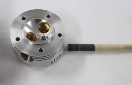
Bronze Valve Cages. I won't bore you with the behind the scenes testing & details of how I eventually landed on this final configuration other than to say model valves & seats don't really 'scale' to a FS engine. The valve 45-deg face is ~.050" across but the seat in the cage is only ~ 0.010". The seat could actually be more, but its actually pretty difficult to machine & finish properly at this scale. When I took apart some commercial RC 4-S engines I was able to see the same thing, teeny thin valve seats.

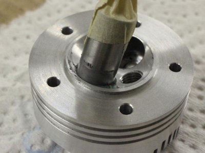
A good method I came across from a successful builder is to insert a known good 'reference' valve into a newly machined cage & pull a vacuum from the top side. If the needle 'holds' meaning it slowly declines over some period like 30 secs, it is deemed good. Turns out this is more difficult than it sounds for many underlying reasons I had to figure out. Its rather humbling when the valve faces look perfect & the needle goes Fffft to zero in a short span. The tester valve has a flat ground on a portion of the stem so the vacuum isn't tricked by the close annular fit of the stem portion.
 

Attachments

  • IMG_2370_edited-1.jpg
    IMG_2370_edited-1.jpg
    95.8 KB · Views: 0
  • IMG_2373_edited-1.jpg
    IMG_2373_edited-1.jpg
    63.4 KB · Views: 0
  • IMG_2389_edited-1.jpg
    IMG_2389_edited-1.jpg
    73.4 KB · Views: 0
  • IMG_2369_edited-1.jpg
    IMG_2369_edited-1.jpg
    84.5 KB · Views: 0

PeterT

Ultra Member
Premium Member
The bronze I'm using is 932. On another post we were discussing the stripey outside of 'bearing bronze'. This has the same look, so just mentioning FWIW - you can maybe distinguish bronze from brass (no stripes) but probably not between bronzes.

Basic turning to size.
 

Attachments

  • IMG_2345_edited-1.jpg
    IMG_2345_edited-1.jpg
    97.1 KB · Views: 0
  • IMG_2346_edited-1.jpg
    IMG_2346_edited-1.jpg
    89 KB · Views: 0
  • IMG_2349_edited-1.jpg
    IMG_2349_edited-1.jpg
    62.9 KB · Views: 0

PeterT

Ultra Member
Premium Member
Flip the cage in the collet chuck. Spot drill, rough drill cage hole drill, inner spot drill, drill stem hole, boring tool to final ID.

Bronze can be a B*tch to hold trueness of small drills I found. It is grabby so very sensitive to tip geometry & drill stiffness. Regular HSS jobber drills were drifting a couple thou on me. Shorter drills improved. Short carbide (which is stiffer) better yet. Eventually I landed on these parabolic HSS drills & magical cutting cream & it just worked like a dream. Why all the fuss? If the valve stem hole is angled even a tiny bit, that influences the way the valve meets the seat & therefore poor seal. I was initialy also reaming the stem holes but I found just the drills were the right combo of fit & trueness.
 

Attachments

  • IMG_2352_edited-1.jpg
    IMG_2352_edited-1.jpg
    125.2 KB · Views: 0
  • IMG_2353_edited-1.jpg
    IMG_2353_edited-1.jpg
    121 KB · Views: 0
  • IMG_2354_edited-1.jpg
    IMG_2354_edited-1.jpg
    106.4 KB · Views: 0
  • IMG_2355_edited-1.jpg
    IMG_2355_edited-1.jpg
    89.2 KB · Views: 0
  • IMG_2356_edited-1.jpg
    IMG_2356_edited-1.jpg
    103.4 KB · Views: 0
  • IMG_2359_edited-1.jpg
    IMG_2359_edited-1.jpg
    152.5 KB · Views: 0
  • IMG_2360_edited-1.jpg
    IMG_2360_edited-1.jpg
    112.1 KB · Views: 0

PeterT

Ultra Member
Premium Member
Initially I was drilling the valve stem hole in the first operation but not getting consistent results. Now, all the operations that influence valve alignment are done in one setting. If the collet/chuck is concentric with the cage body & drilling went well, the exit hole should be concentric.
 

Attachments

  • IMG_2385_edited-1.jpg
    IMG_2385_edited-1.jpg
    76.7 KB · Views: 0
  • IMG_2398_edited-1.jpg
    IMG_2398_edited-1.jpg
    98.7 KB · Views: 0

PeterT

Ultra Member
Premium Member
This leaves the seat cutting job. The edge of the cage is colored with dark Sharpie. I use a 45-deg reamer cutter with a modified pilot pin to match my 3mm stems. The cutters are used by gunsmiths, sorry I don't know what for exactly but they are sharp & accurate. Cutting the seat is kind of a light feel thing. It doesn't photo well without lighting banding but we are looking for a uniform consistent shiny band about 0.010" wide. If its even non-uniform something went amiss & will likely fail the vacuum test miserably.
 

Attachments

  • IMG_2363_edited-1.jpg
    IMG_2363_edited-1.jpg
    129.9 KB · Views: 0
  • IMG_2366_edited-1.jpg
    IMG_2366_edited-1.jpg
    96.4 KB · Views: 0
  • IMG_2364_edited-1.jpg
    IMG_2364_edited-1.jpg
    65.5 KB · Views: 0
  • IMG_2368_edited-1.jpg
    IMG_2368_edited-1.jpg
    95.2 KB · Views: 0

PeterT

Ultra Member
Premium Member
Last job on the heads before bonding the valve cages is cutting the cooling fins with 0.045" slitting saw ~ 0.200" deep about 0.025" DOC per pass. About 200 rpm felt right on 3" OD cutter. This is a messy, mind numbing job. Its important to keep a steady feed rate, use lots of WD-40, clean the teeth & trench of swarf between passes because there is very little clearance & aluminum is a gummy material. I've read horror stories where guys folded up the cutter on the proverbial 'last pass' & at this stage a lot of work has gone into the part.
 

Attachments

  • IMG_2245_edited-1.jpg
    IMG_2245_edited-1.jpg
    119.6 KB · Views: 0
  • IMG_2403_edited-1.jpg
    IMG_2403_edited-1.jpg
    176.5 KB · Views: 0
  • IMG_2402_edited-1.jpg
    IMG_2402_edited-1.jpg
    115.8 KB · Views: 0

PeterT

Ultra Member
Premium Member
Deburring & cleanup. Last step is permanent bonding of cages into heads & making the inlet/outlet cross holes.
Family shot before Xmas break.
 

Attachments

  • IMG_2408_edited-1.jpg
    IMG_2408_edited-1.jpg
    104.4 KB · Views: 0
  • IMG_2406_edited-1.jpg
    IMG_2406_edited-1.jpg
    116.4 KB · Views: 0
  • IMG_2409_edited-1.jpg
    IMG_2409_edited-1.jpg
    149.8 KB · Views: 0

PeterT

Ultra Member
Premium Member
Carrying on with the permanent valve cage installation. I did some hole conditioning with fine lapping compound, it left the hole a nice mat finish. Then everything was cleaned spotless with thinner, acetone & many Q-tips. The cages are an easy slip fit into the holes being about 0.001-0.002" diameter undersize which is on the low allowable end recommended for Loctite 680 high temp retaining compound. I discovered a rather amazing thing happens (fortunately on a prior tester). Something about bronze & aluminum, possible copper content or the combinations, the working time is dramatically decreased. You don't have a lot of doddle time to position it or twirl it around for even coating before it kicks off. I tried some scrap parts with steel & brass to see if I was hallucinating & those alloys behave normally, ample working time. Anyways the cages all landed in correct position. Allowed a day to cure before machining.

Then onto the fixture for spot drill, gas passage hole, counterboring, tapping (7/16-28). I think I already mentioned the holes enter the head at a weird angle so the tap threads only catch on one side for a bit & unfortunately through the cooling fins which is a PITA. I found the best way was lock the tap in the TS chuck & just gently push the TS casting body straight into the hole as I turned the chuck with my other hand. Reverse the direction about every half turn to break the chip & continue on. Then repeat this with a bottoming tap with all the end threads ground off to get the last 3 or 4 threads as deep as I can. One new learning was that Tapmatic cream lube really does work better than either the aluminum or regular cutting fluids I use. You can feel it has less resistance. Its really important to vacate the tapping chips often so the compressor nozzle was always close by.
 

Attachments

  • IMG_2419_edited-1.jpg
    IMG_2419_edited-1.jpg
    51.4 KB · Views: 5
  • IMG_2422_edited-1.jpg
    IMG_2422_edited-1.jpg
    56.7 KB · Views: 0
  • IMG_2427_edited-1.jpg
    IMG_2427_edited-1.jpg
    56.7 KB · Views: 0
  • IMG_2429_edited-1.jpg
    IMG_2429_edited-1.jpg
    56.8 KB · Views: 0
  • IMG_2431_edited-1.jpg
    IMG_2431_edited-1.jpg
    61.2 KB · Views: 0
  • IMG_2434_edited-1.jpg
    IMG_2434_edited-1.jpg
    64 KB · Views: 0
  • IMG_2445_edited-1.jpg
    IMG_2445_edited-1.jpg
    53.8 KB · Views: 1
Last edited:

PeterT

Ultra Member
Premium Member
There are a lot of sharp angles & fragile corners & variable geometry created by the combination of the side entry port hole, the threads & the cooling fins. I found the best treatment was these green rubberized abrasive in a Dremel on low speed. They are dirt cheap on AliExpress. They do wear but you can reshape them with 60-80 grit blue sandpaper. The rubber shrapnel washes off easy with thinner or WD-40. I was paranoid of messing up my valve seat during all these operations while they were exposed to machining & conditioning. I usually had tape covering them but I also had to debur the edge of the bronze port hole. I had an afterthought maybe I could have applied a bead of glue gun glue as a temporary barrier but I didn't want to experiment at this stage of the game.
 

Attachments

  • IMG_2444_edited-1.jpg
    IMG_2444_edited-1.jpg
    44.3 KB · Views: 4
  • IMG_2436_edited-1.jpg
    IMG_2436_edited-1.jpg
    48.2 KB · Views: 4
  • IMG_2448_edited-1.jpg
    IMG_2448_edited-1.jpg
    34.1 KB · Views: 4
  • IMG_2449_edited-1.jpg
    IMG_2449_edited-1.jpg
    54.5 KB · Views: 1
  • IMG_2451_edited-1.jpg
    IMG_2451_edited-1.jpg
    52.8 KB · Views: 1

PeterT

Ultra Member
Premium Member
Valve spring retainers made from 303 stainless. Fiddly little buggers.
In hindsight I probably made them bass-akwards, I could have done all the ops in one setting with the cup side facing out. Oh well.
 

Attachments

  • IMG_2410_edited-1.jpg
    IMG_2410_edited-1.jpg
    135.1 KB · Views: 0
  • IMG_2413_edited-2.jpg
    IMG_2413_edited-2.jpg
    149.2 KB · Views: 0
  • IMG_2415_edited-1.jpg
    IMG_2415_edited-1.jpg
    143 KB · Views: 0
  • IMG_2417_edited-1.jpg
    IMG_2417_edited-1.jpg
    93.3 KB · Views: 0
  • IMG_2418_edited-1.jpg
    IMG_2418_edited-1.jpg
    91.7 KB · Views: 0

PeterT

Ultra Member
Premium Member
A dozen nuts made from 0.5" 303 stainless hex. These retain the (end flared) intake & exhaust tubes in the head. The thread relief groove is made using Nicole radiused insert of 1.5mm (0.059") diameter. The groove width doesn't allow for much error in reaction time to disengage the lathe threading half nuts. I didn't consider until I got going the thread point has to terminate in the middle of the circular groove which is only half the groove width. Not that I have a lot of threading experience but I am sold on these Ebay/Ali threading inserts. I was concerned my lathe rpm might be too slow for the carbide in this particular application, but they cut nicely.
 

Attachments

  • IMG_2452_edited-1.jpg
    IMG_2452_edited-1.jpg
    105.2 KB · Views: 1
  • IMG_2460_edited-1.jpg
    IMG_2460_edited-1.jpg
    139.4 KB · Views: 1
  • IMG_2462_edited-1.jpg
    IMG_2462_edited-1.jpg
    106.6 KB · Views: 1
  • IMG_2467_edited-1.jpg
    IMG_2467_edited-1.jpg
    98.7 KB · Views: 1
  • IMG_2468_edited-1.jpg
    IMG_2468_edited-1.jpg
    110 KB · Views: 1
  • IMG_2469_edited-1.jpg
    IMG_2469_edited-1.jpg
    80.3 KB · Views: 1
  • IMG_2471_edited-1.jpg
    IMG_2471_edited-1.jpg
    113 KB · Views: 1
  • IMG_2472_edited-1.jpg
    IMG_2472_edited-1.jpg
    107.3 KB · Views: 1

John Conroy

member
Premium Member
You have gotten a lot done in the last couple of months! I'm going to have to make a trip down to Cowtown soon to check out all those beautiful parts in person.Amazing work Peter!
 

PeterT

Ultra Member
Premium Member
Thanks John. Its back to work on Monday from Xmas time off, so the pace might slow down a bit with only the evening shift LOL.
Look forward to the visit.
 

PeterT

Ultra Member
Premium Member
Yeah that discussion comes up a lot on the model engine forums. The bottom line is that it just doesn't seem to work, even by experienced builders. But the reasons are maybe not well understood. People have lots of experience doing this with full size engines but many things like this just don't 'scale down' the same way. Unfortunately the combustion temperature is about the same, the seal requirement is the same, but the surface contact area of FS engine is exponentially larger. Much higher valve spring force on a FS engine but it would be interesting to know force/contact area comparison.

Home made model valves are rarely hardened because the skinny shape would surely distort during quench. You would have to turn them oversize from some kind of tool steel & grind them all over which would be challenging at this size. So we are kind of stuck with the base alloy hardness. FS valves are tougher/harder material and are precision ground on the stems & valve faces. A lot of guys make a big deal about setting the lathe compound at some angle (lets say is 45.4 deg vs target of 45.0) but leaving it this way for all seat operations on both valve & cage so its the same. Personally I find this impractical & my own testing has shown the machining itself is way more critical (the micro record player grooves). Theoretically you could have a flat valve seat and a slightly convex curved valve face and it will point contact seal. I actually think this is what might be going on so some degree when we polish the valve face. Its not how you would do things a real FS engine obviously but we do what we have to to get the job done.

I'm not really sure about valve lapping aspect in FS engines to be honest. Typically in lapping, the material which is softer than the other will be the embedder of lapping compound. It becomes a cutting 'form tool' to remove material from the other surface. In my case the valves are 303 stainless which is 83 RB hardness, the cage/seat is 544 bronze which is only 40 RB. So by this it seems like the lapping abrasive would become embedded in the narrow bronze seat & basically wear a thin ring on the valve face? This is kind of what I saw fiddling around with some testers. So it might better to have a dedicated lapping tool that gets the wear but which you can re-surface back to 45-deg. I made one out of brass for future tune-up. So far it is showing the wear ring even though the hardness is quite similar to bronze.

I really cant speak for FS engines, maybe some of you know the relative hardness between valve & seat. Supposedly when you have two more equal hardness surfaces, the abrasive does more of a rolling cutting action & both surfaces wear to one another. I think cast iron acts a bit differently in lapping. Even though it is very hard compared to other steel alloys, it has a matrix of open pores from the carbon inclusions & these form natural pockets for the abrasive to lodge in & thus it becomes the sandpaper 'lap'. But I don't think FS engines have integral cast iron valve seats anymore do they?

All I know is a 4S model engine I disassembled has this same bronze valve seat with a tiny band of area & we run the crap out of them. Someone more knowledgeable than me said the valve fit must be very close to begin with but then it basically micro-peens itself to a final fit. I'm not sure about this & I intend to test the hardness of the commercial valve. But I'm basically following the recipe of others who have gone down this path before me.
 

Attachments

  • IMG_2043_edited-1.jpg
    IMG_2043_edited-1.jpg
    87.8 KB · Views: 2

PeterT

Ultra Member
Premium Member
Cylinder making time. When I modified my heads to a slightly larger diameter, I assumed they would look OK mounted to the (now relatively smaller) diameter stock cylinders. But once I had the tester assembled, my eyes decided it didn't look right so I expanded the diameter of the cylinder to suit. This created a few cascading headaches changing the taper, the skirt relief, layout & depth of the cooling fins. So I spent some time on the computer adjusting things. I think the effort was worth it in the end.

They start out as drops of 6061-T6. I rough drilled them 7/8" in a batch just to get it over with. Then each is chucked & machined basically to completion to preserve the setup: bored to 0.005" undersized with single point CCMT carbide boring bar & reamed (1.0625"). Consistent ID & finish is kind of important because the liners will be lapped to a specific OD & heat shrunk into the cylinder.
 

Attachments

  • IMG_2494_edited-1.jpg
    IMG_2494_edited-1.jpg
    103.5 KB · Views: 0
  • IMG_2497_edited-1.jpg
    IMG_2497_edited-1.jpg
    113.2 KB · Views: 0
  • IMG_2498_edited-1.jpg
    IMG_2498_edited-1.jpg
    121.3 KB · Views: 0
  • IMG_2500_edited-1.jpg
    IMG_2500_edited-1.jpg
    216.6 KB · Views: 0

PeterT

Ultra Member
Premium Member
Series of basic turning ops.
Lots of swarf heading for my motor - but the new screen door is on... no room at the Inn! LOL
 

Attachments

  • IMG_2506_edited-1.jpg
    IMG_2506_edited-1.jpg
    128.2 KB · Views: 0
  • IMG_2510_edited-1.jpg
    IMG_2510_edited-1.jpg
    128.6 KB · Views: 0
  • IMG_2512_edited-1.jpg
    IMG_2512_edited-1.jpg
    54.4 KB · Views: 0

PeterT

Ultra Member
Premium Member
Fin grooving using 0.043" wide Nikcole insert. They cut like a dream, just keep a bit of aluminum cutting fluid on it. The depths are slightly different so I had to have my notebook handy. The top 3 grooves are a bit shallower to accommodate the threaded head bolts. The next 3 are limited by maximum DOC of the insert. I want to say its about 0.220". Then the remainder grooves are one constant diameter which then matches the skirt diameter. I chamfered the edges with one of those HSS triangular scraper & parted it off.
 

Attachments

  • IMG_2515_edited-1.jpg
    IMG_2515_edited-1.jpg
    52.9 KB · Views: 0
  • IMG_2516_edited-1.jpg
    IMG_2516_edited-1.jpg
    82.5 KB · Views: 0
  • IMG_2519_edited-1.jpg
    IMG_2519_edited-1.jpg
    66.6 KB · Views: 0

PeterT

Ultra Member
Premium Member
Machinable expansion arbor holds the cylinders so they can be machined to length.
 

Attachments

  • IMG_2522_edited-1.jpg
    IMG_2522_edited-1.jpg
    48.1 KB · Views: 0
  • IMG_2523_edited-1.jpg
    IMG_2523_edited-1.jpg
    62.5 KB · Views: 0
  • IMG_2525_edited-1.jpg
    IMG_2525_edited-1.jpg
    50.3 KB · Views: 0
  • IMG_2526_edited-1.jpg
    IMG_2526_edited-1.jpg
    50.3 KB · Views: 0
Top