• Spring 2024 meetup in Calgary - tentative date Saturday, April 20/2024. Other regions are also discussing meet ups. If you want one in your area get going on organizing it! discussion
  • We are having email/registration problems again. Diagnosis is underway. New users sorry if you are having trouble getting registered. We are exploring different options to get registered. Contact the forum via another member or on facebook if you're stuck. Update -> we think it is fixed. Let us know if not.
  • Spring meet up in Ontario, April 6/2024. NEW LOCATION See Post #31 Discussion NEW LOCATION

Power drawbar on my Bridgeport clone mill

John Conroy

member
Premium Member
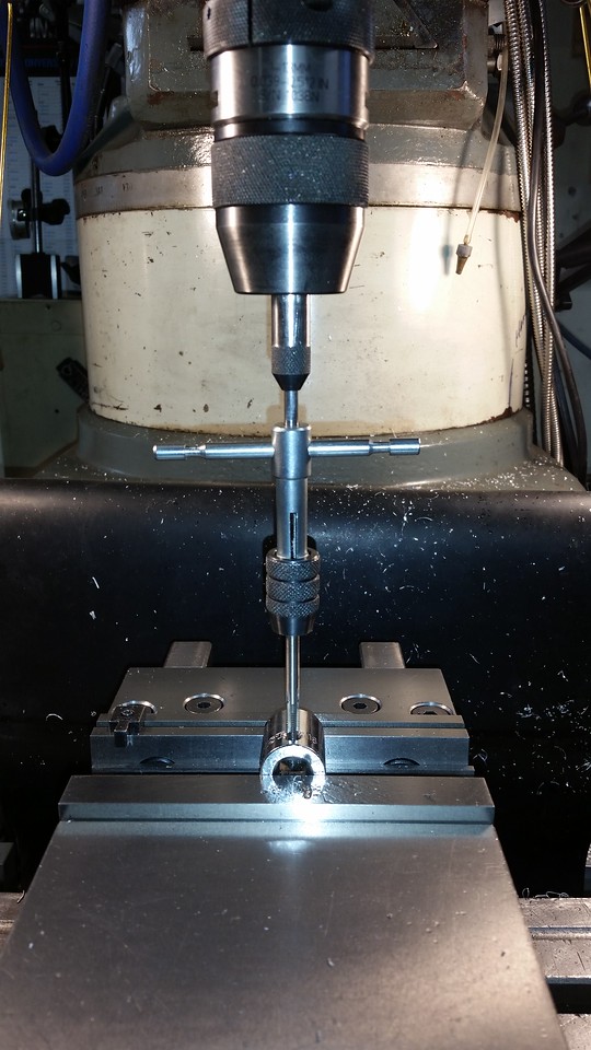
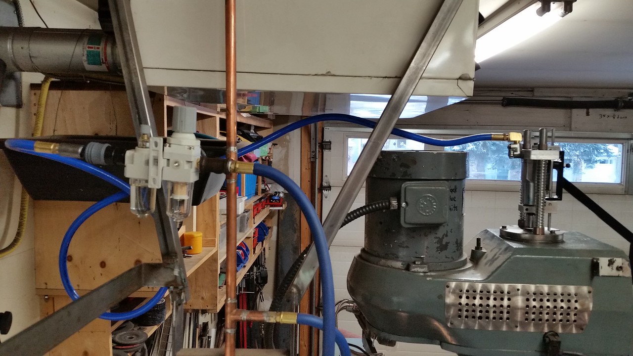
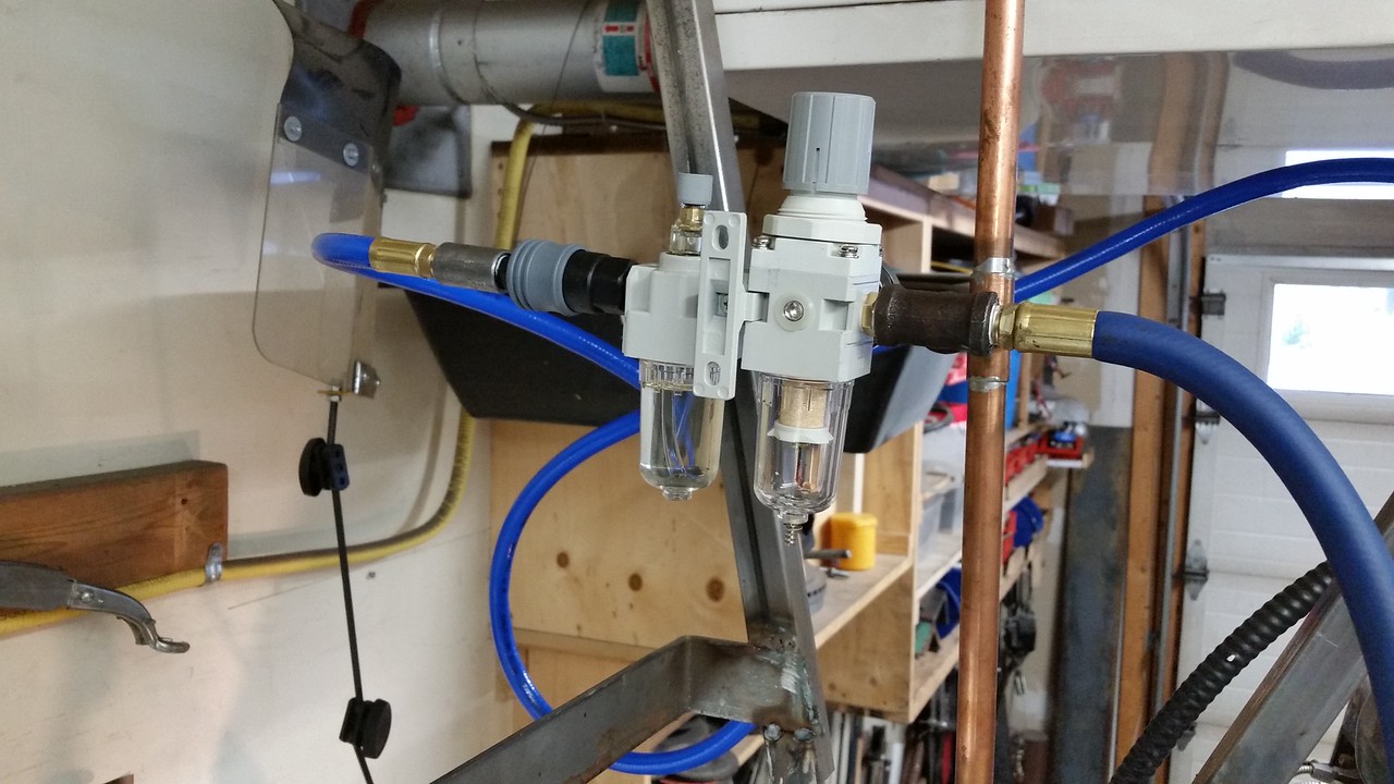
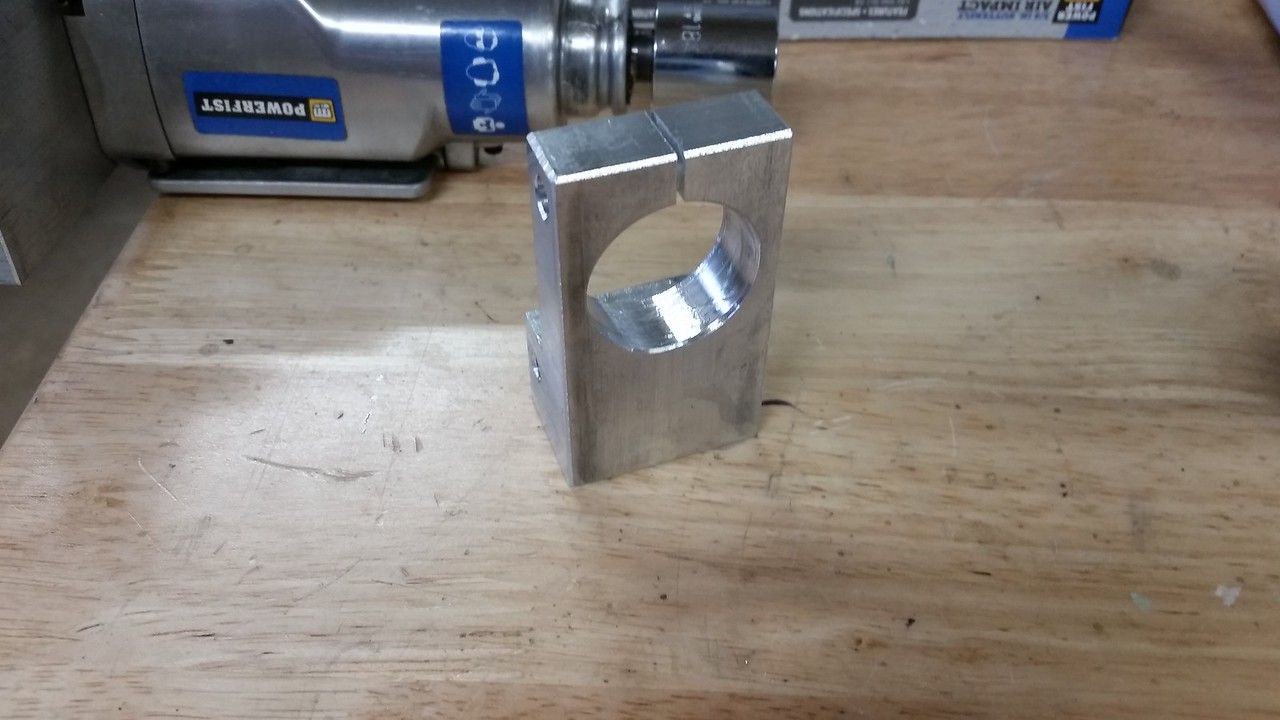
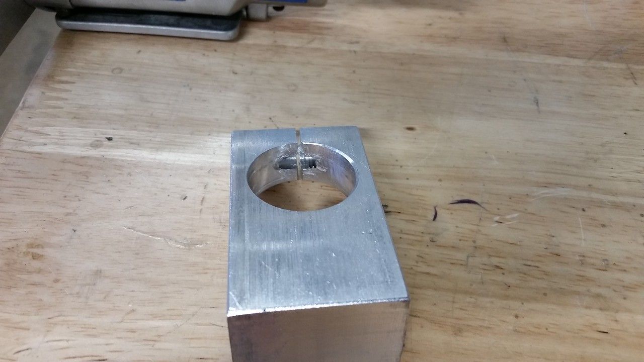
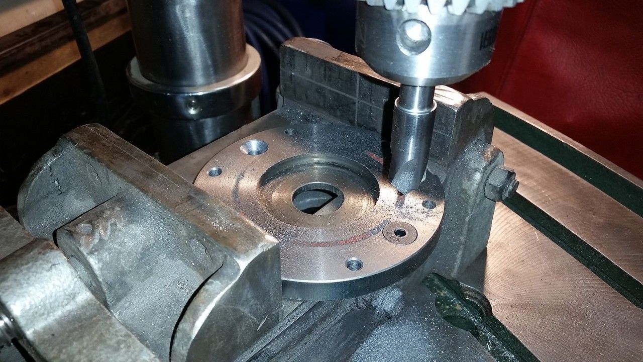
A few months ago I installed a 6 inch riser block under the ram of my knee mill. While this allows a lot more room under the spindle for accessories like drill chucks and rotary tables, it makes changing tools a pain. Since I am a short guy I have to climb a step stool to get to the drawbar bolt head. There are plenty of videos on YouTube about this so I took some ideas and went ahead with my version using mostly stuff I had on hand already. I had to buy the impact wrench from PA and the springs at Lowes but the rest came from my stock of junk and scraps. When I bought my mill it came with an extra head to use for spare parts so I had an extra top spindle plate so I machined it flat on both sides to use as the base plate. I removed the rubber guard off the end of the impact and measured the nose and used a scrap chunk of 6061 AL to make the bottom clamp for the impact. The pinch bolt is 1/4-20.


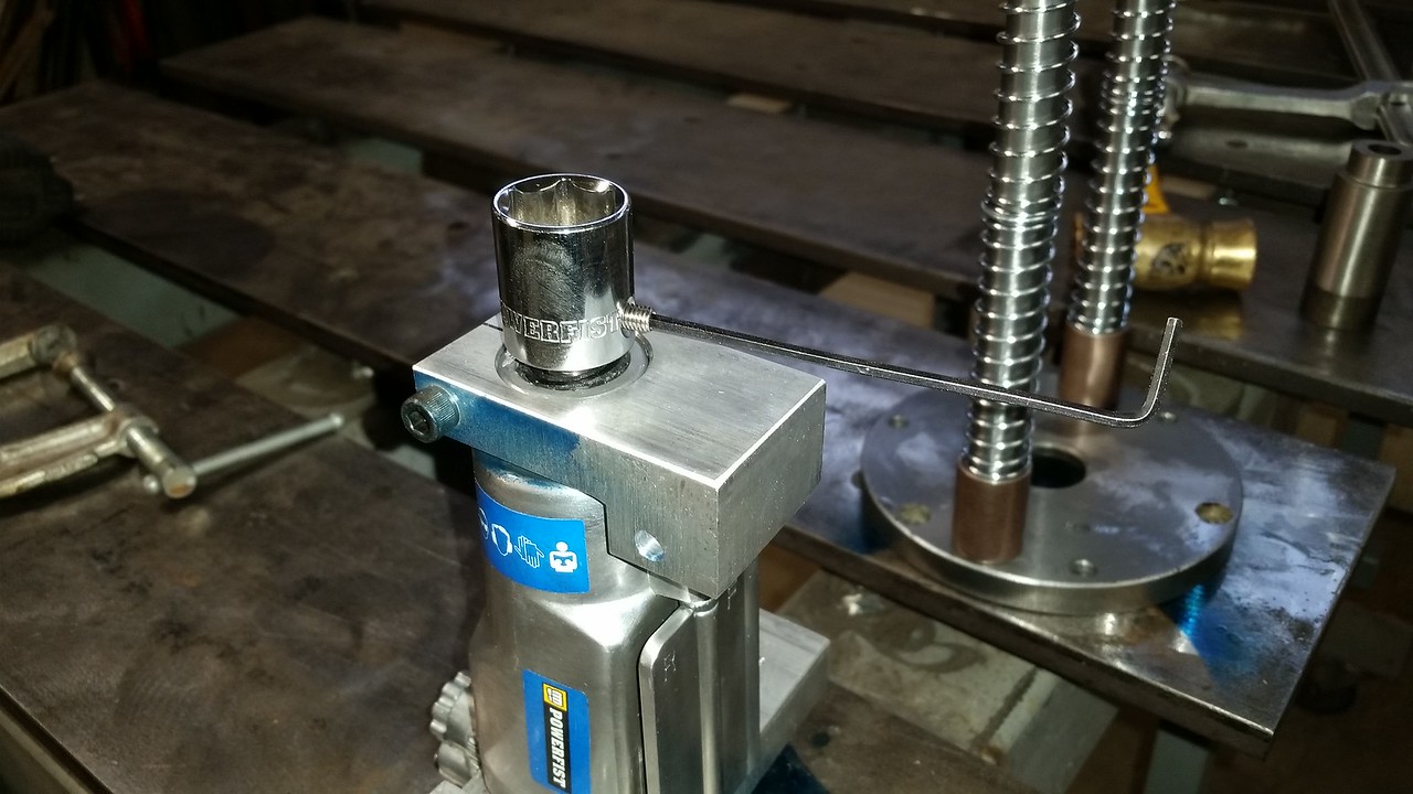
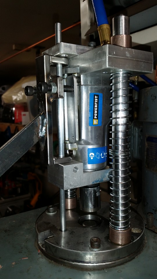
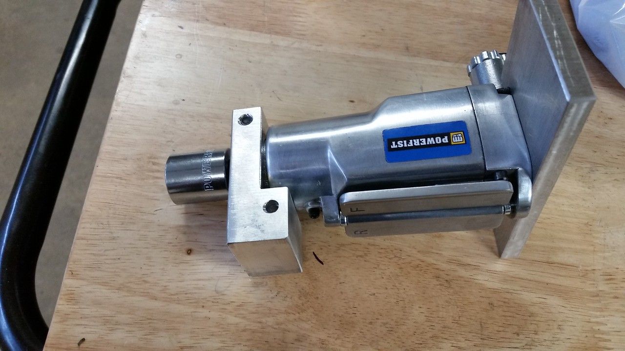
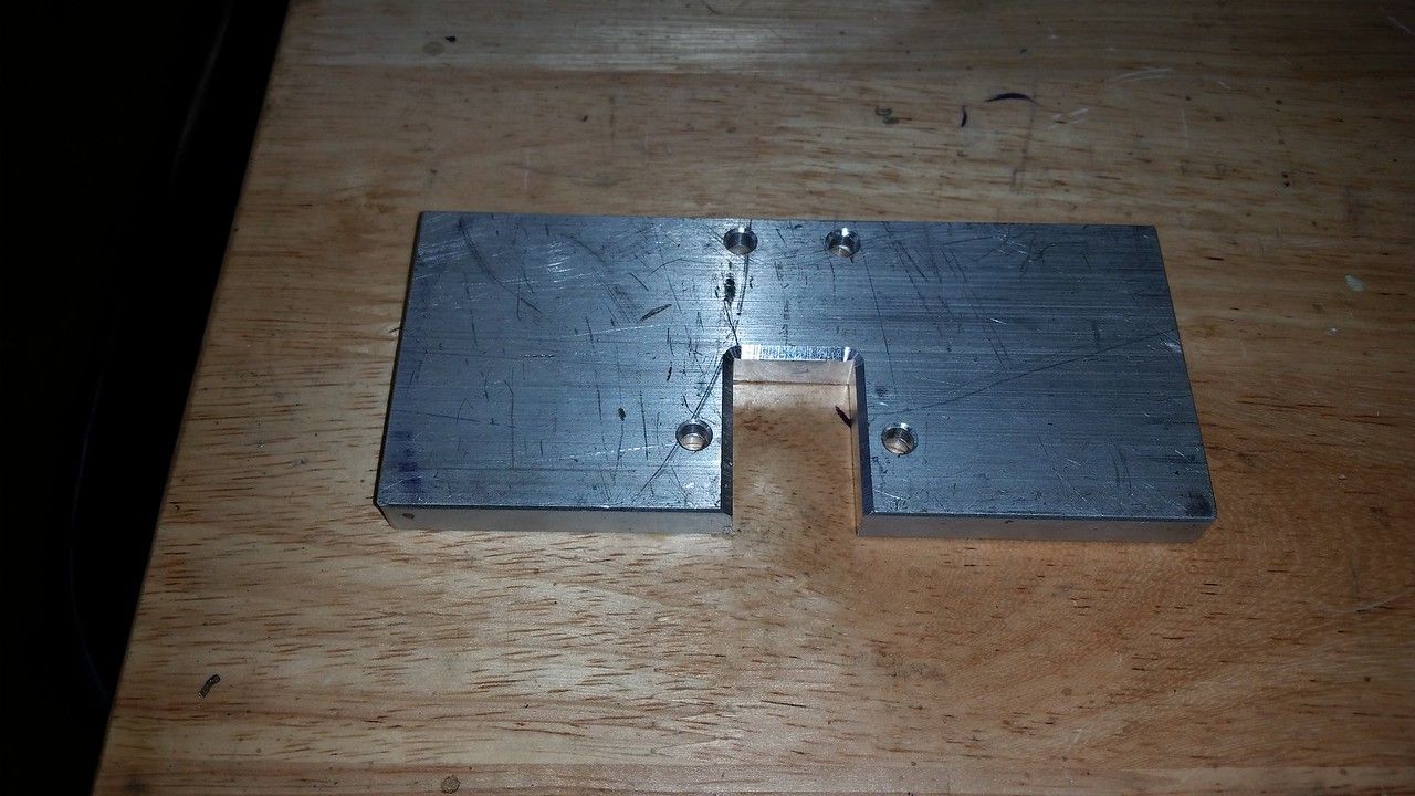
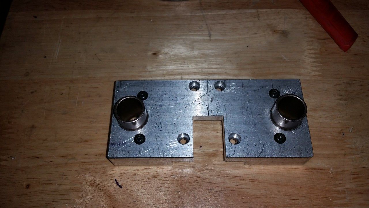
The top bracket was machined from another chunk of 6061. I used some 5/8" drill rod for the guide rods and had some bronze 5/8" ID bushings that worked for me. I bore the holes in the top bracket for a .002" interference fit to the 3/4" OD of the bushings. The base plate is 5" diameter so I made the guide rods 4" apart on center. I transfer punched the original endcap screw holes on the impact for the pattern on the top bracket and used longer M4 X 30 screws to hold it in place. I lined up the center of the 3/8" square drive on the impact with the bushing bores.


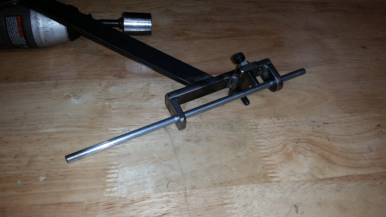
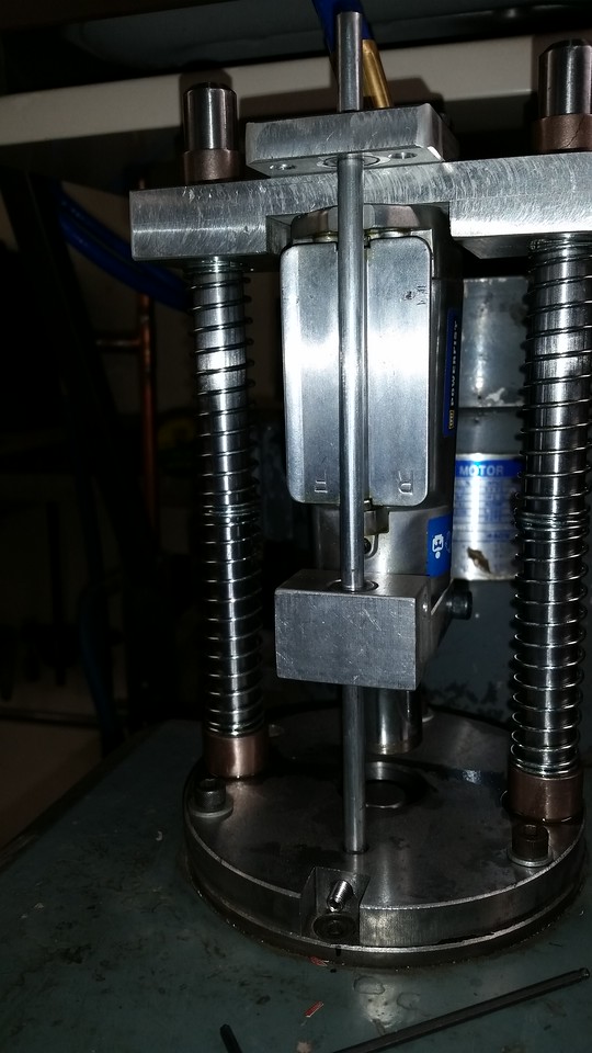
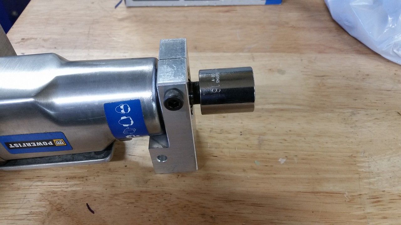
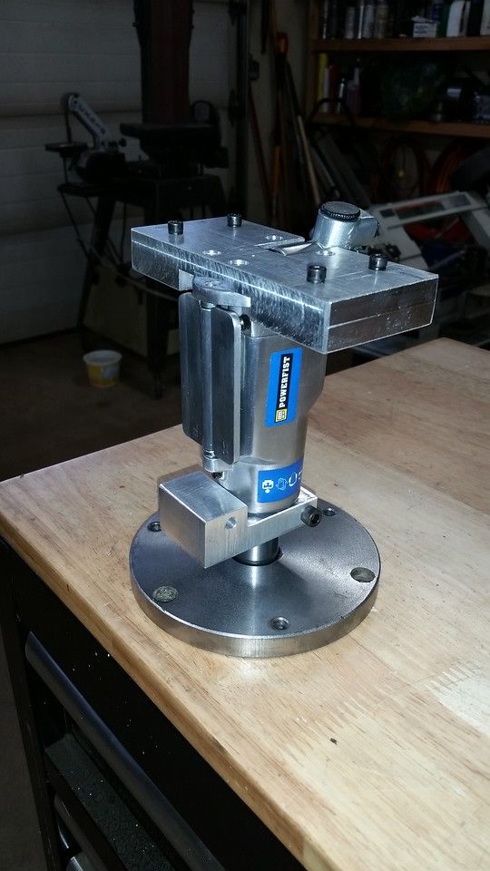
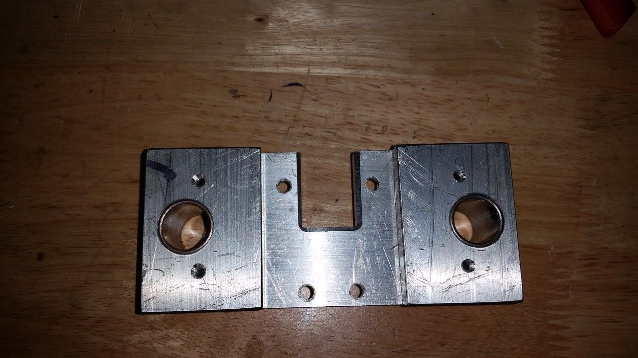
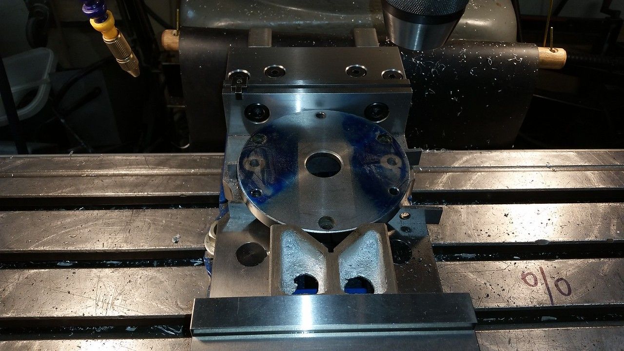
Here you can see the top and bottom plates as well as the lower bracket mocked up.


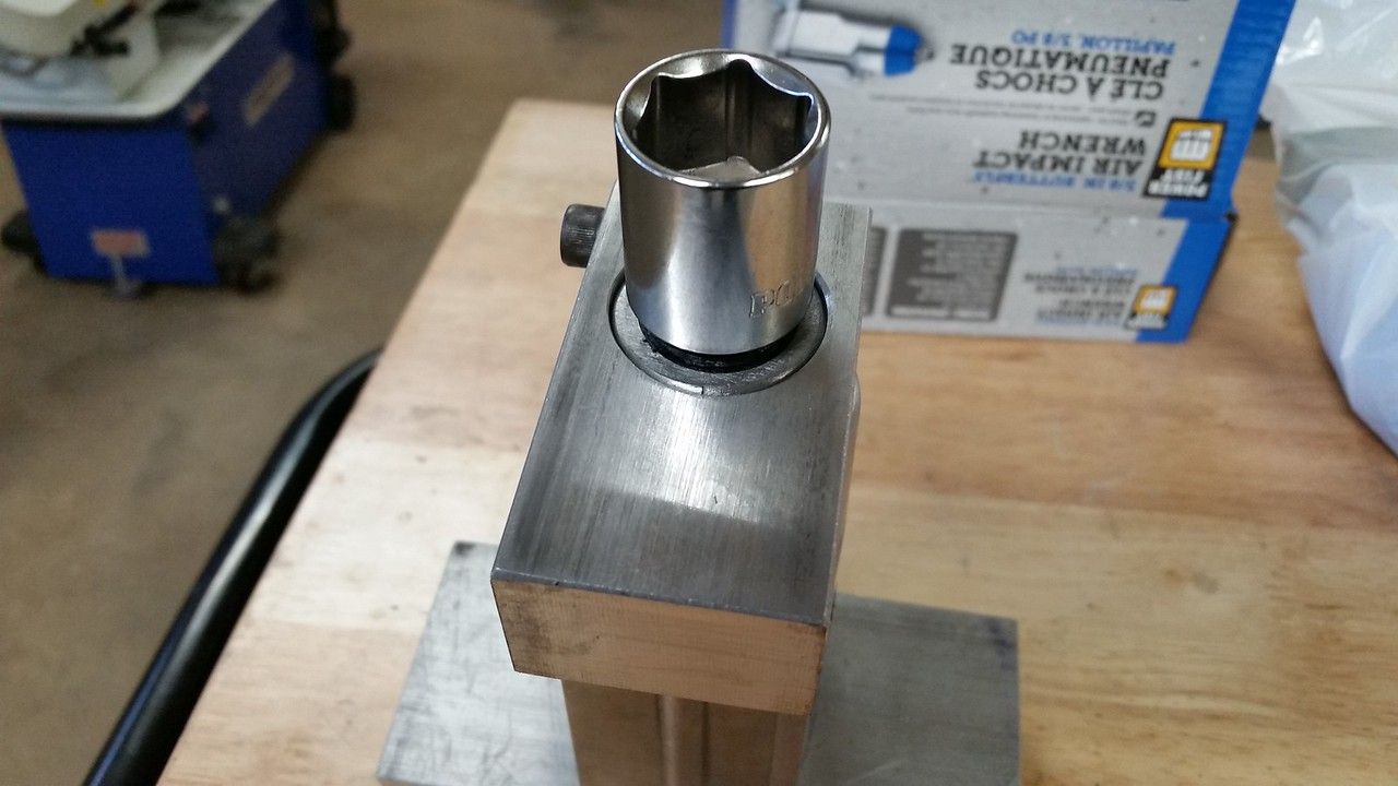
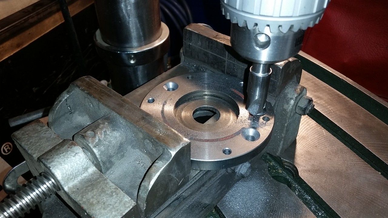
I wanted plenty of thickness to support the bushings so I bolted small pieces of the same 6061 to each end of the top bracket to make the thickness 3/4" and did the boring with the pieces all bolted together.


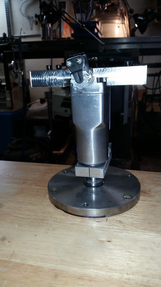
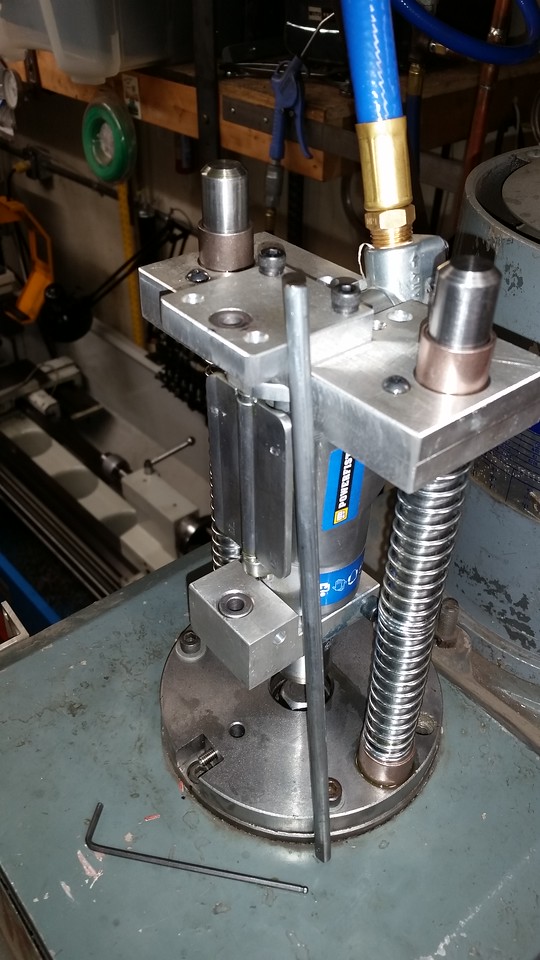
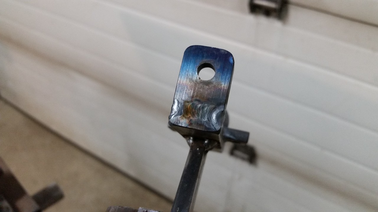
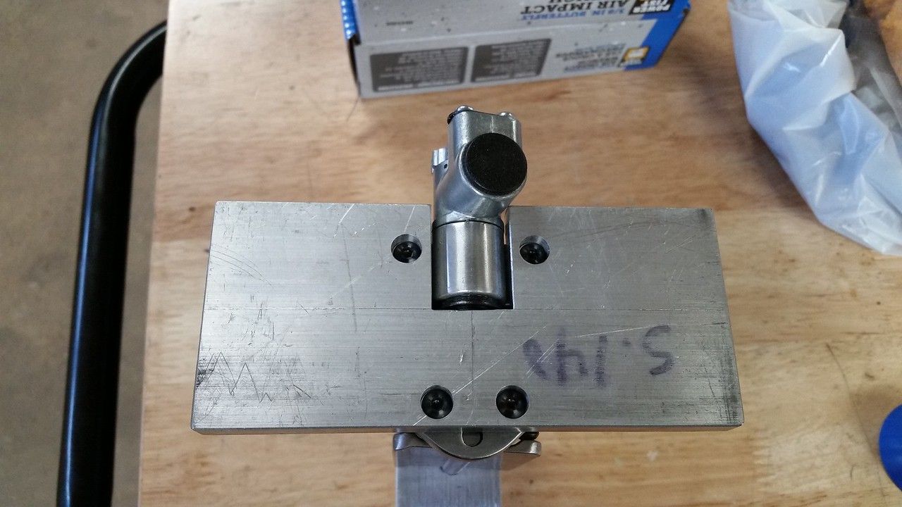
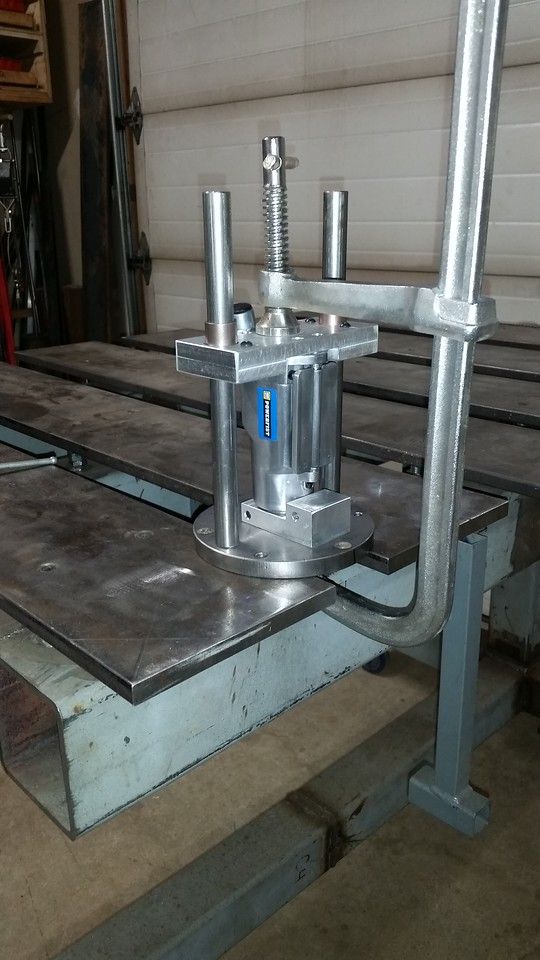
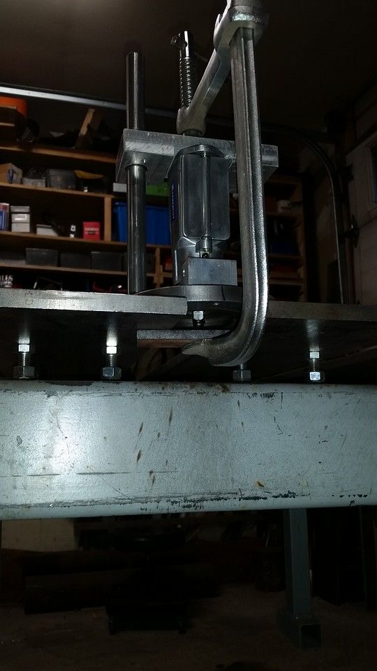
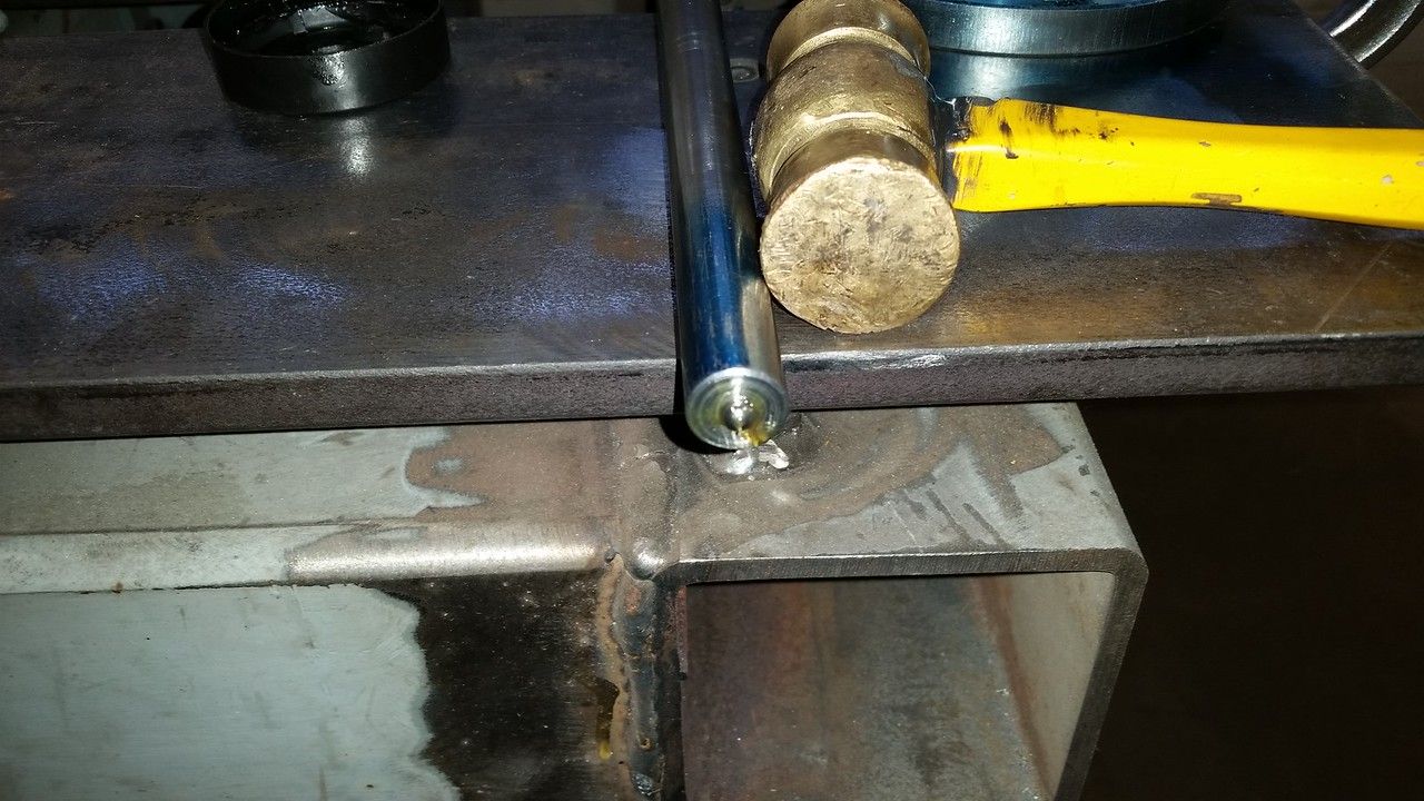
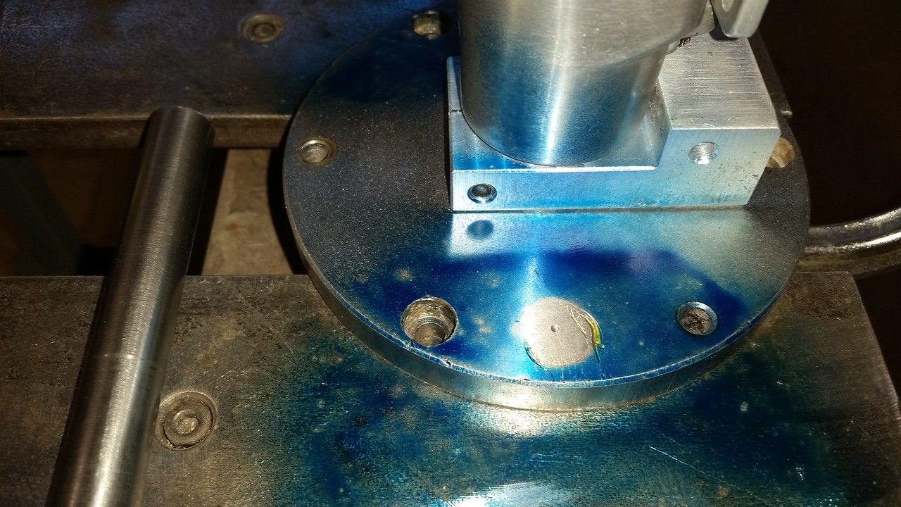
I clamped the pieces together in mock up on the welding table with the drive end of the impact centered in the hole in the bottom plate and with the guide rods sitting in the bushings. I had previously center drilled the bottom of the guide rods so I used grease to stick a 1/8" ball bearing to the end of each rod and gave them a tap with a hammer to act like a transfer punch and make a drill mark on the bottom plate. The marked spots were corrected to exactly 4" on center and drilled to 5/16" then countersunk for fasteners from the bottom of the plate into threads drilled and tapped into the guide rods.


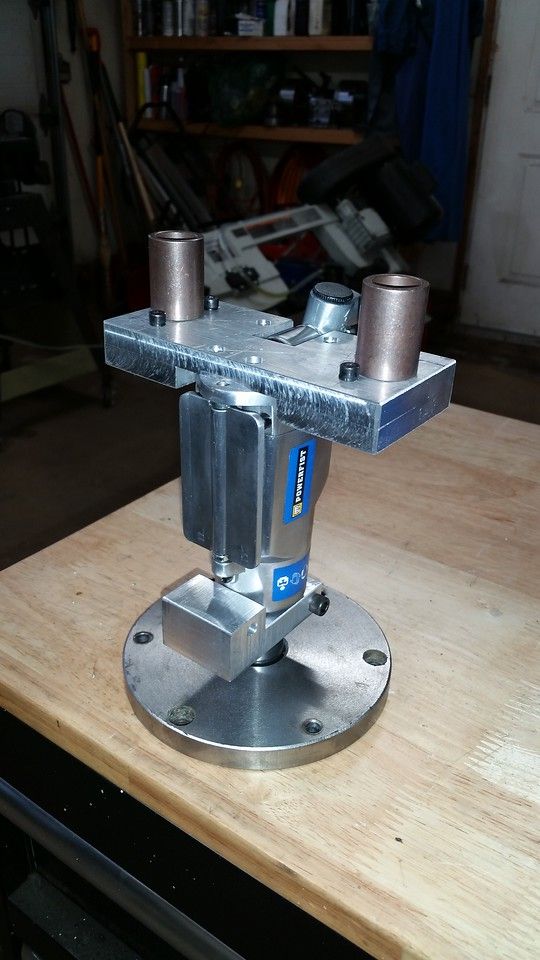
More to come before it's finished
 

Tom Kitta

Ultra Member
You reminded me of this project - I have same brand new butterfly PA air tool. Some guy makes them and sells on eBay but wants a lot of money for them - I think like $200 USD plus shipping.
 

John Conroy

member
Premium Member
Thanks for your comments guys. When I was planning to build this I read some discussion on line regarding using linear bearings rather than bushings on the guide rods. Some people said they had encountered sticky movement when pulling the unit downward to engage the socket onto the top of the drawbar. I thought this was probably due to misalignment during the build as I looked at the YouTube video on Tom's Techniques and he didn't have any reported problem using bushings.

<iframe width="560" height="315" src="
" frameborder="0" allow="accelerometer; autoplay; clipboard-write; encrypted-media; gyroscope; picture-in-picture" allowfullscreen></iframe>

Well I was very careful to get the guide rods aligned to the bushings and the socket aligned with the drawbar but I still encountered the binding, maybe because my bushings are much shorter than Tom's. So I looked at some more videos and this one by Mike Gaspard caught my eye for a couple of reasons. First I didn't really like the idea of bolting the handle direactly to the butterfly handle on the impact and also because he used bearings and his is a nice simple design.

<iframe width="560" height="315" src="
" frameborder="0" allow="accelerometer; autoplay; clipboard-write; encrypted-media; gyroscope; picture-in-picture" allowfullscreen></iframe>

But I thought maybe I could salvage the bushing design with a third guide rod to prevent some of the tipping motion caused by the handle resulting in binding of the bushing on the 2 main guide rods. So modified the 2 brackets that hold the impact by adding bushings for a 1/4" guide rod through them. The extra rod is anchored into the base with a M5 set screw. This has made a world of difference but there is still some binding at times. I also found that the little friction ring on the end of the impact does not keep the socket in place so I drilled and tapped the socket for another M5 set screw. By milling a very small dimple into the square drive on the impact the set screw can enter the dimple but not tighten onto the square drive. This still allows the socket some movement to aid alignment but prevents the socket from flying off. After deciding on the correct depth for the set screw I used red Loctite to keep it in place. I still have a few minor details to sort out but I am going to run it like this for now and see how it functions.


PeterT

Ultra Member
Premium Member
Nice work. Right now I can reach my drawbar nut on tippy toes & use my Milwaukee cordless torque wrench.
One thing I've always wondered about - the odd time a tool arbor will stick in the taper section. If I don't feel the tool it coming loose on it sown, I just un-screw a few threads worth & give light tap on top of nut to loosen, then carry on with removal. How do the more automated power systems like yours work in this regard since the nut is now covered up?
 

John Conroy

member
Premium Member
Time will tell how that works out Peter but I think the vibration of the impact will break the grip of the taper.
 

John Conroy

member
Premium Member
Final pieces to the project for now. I wanted to reduce the power of the impact, it has a 5 position selector on it but even with it on the lowest setting it would over torque. I ordered a regulator and in line oiler (Amazon) as it will surely get neglected. I have set the pressure to 75 PSI and that seems be plenty to tighten the draw bar as much as I would by hand. I also added a right angle fitting at the impact to keep the hose away from my furnace.


John Conroy

member
Premium Member
Another modification to the power drawbar. I found that it was too easy to move the handle to one side or the other as the only resistance is the tiny springs in the impact air valves. I added a flat plate and 2 springs that keep the handle in the center position and require more effort 20201219_133123.jpg to run the impact. It has much better feel now. I'm still undecided if I am going to switch from the bushings to linear bearings on the main guide rods. I'm also going to change the socket to a 12 point one so it lines up with the drawbar more easily. Linear bearings and socket are ordered.
 

PeterT

Ultra Member
Premium Member
Looking good, keep us posted.
I meant ask about that inline oiler thing. Does the compressed air circulate through the little bath, become a oily vapor to lubricate downstream parts? Or is there like a mixture setting?
 

John Conroy

member
Premium Member
There is a little tube in the oil bottle and the top of the tube is in the air flow. As the air goes past the top of the tube it draws a little oil up into the air stream and into the impact air line. There is a screw adjuster to control how much oil enters the air stream. I oil the rest of my air tools manually but this one would be a pain so I went with this.
 

John Conroy

member
Premium Member
I finally got the 16 mm linear bearings and bored the top bracket to accept them keeping the 4 inch center to center spacing. Even on the 5/8" rods (.005" under 16 mm) it is much smoother and has less friction than with the bronze bushings. If you're going to build one of these the bearing are a worthwhile expense.

20210115_185306.jpg 20210115_185300.jpg 20210115_190429.jpg
 

PeterT

Ultra Member
Premium Member
Looking good! I've been curious about those linear bearings. I've always assumed you probably should buy the corresponding precision shaft at the same time, did you do that? If so, how is the material to machine like cutting, turning ends etc?
 

Janger

(John)
Administrator
Vendor
John - This looks great as usual. Can I ask you to please post a video showing you loading and unloading a tool? How many hours do you think this project took?
 

John Conroy

member
Premium Member
Looking good! I've been curious about those linear bearings. I've always assumed you probably should buy the corresponding precision shaft at the same time, did you do that? If so, how is the material to machine like cutting, turning ends etc?

These are the bearings I bought.

https://www.amazon.ca/uxcell®-LM16U...0910428&sprefix=16+mm+linear+,aps,217&sr=8-16

I was going to order this shaft but I already had used 5/8" drill rod when the bushings were the plan. The bearings work on the 5/8" rod but there is a little play as 5/8" is about .005" less than 16mm. If I was to do it again I would go with the bearings from the start but I would still order 16mm drill rod from KBC. It is easy to work with and is about the same price as the linear bearing shaft. It sounds like the linear shafting is really hard and may be a bear to machine. The description says "HIGH HARDNESS: Adapting C45 high quality steel, high frequency quenching, surface chromium plating(10um-20um). The case hardness could be reach to 55-60 HRC. Durable and corrosion-resistant."

https://www.amazon.ca/Linear-Motion...0910816&sprefix=16+mm+linear+,aps,217&sr=8-17

https://www.kbctools.ca/itemdetail?auto=1&itemcode=1-950M-016

I also switched to a 12 point socket and machined a small taper on the top of the drawbar to aid the socket engagement. I am going to post a video as Janger suggested and you can see the tapered top on the drawbar in the video.
 
Top