Dan Dubeau
Ultra Member
Figured I'm a good ways into building this now, so I better start a thread to keep me focused lol
A couple months ago I picked up some forklift forks with the intention of making a striking anvil stand for a post vise I bought about 6-7 years ago. I also wanted to make some swage blocks and other forming aids, more to come on those later.
Last weekend I started cutting them up. While that was cutting, I cut up an old trailer leaf spring to replace the missing spring on the vise.


The swage blocks will be 12" long, so I zipped off three of them with the remaining length
I was rolling around some ideas all week on how to do this, and had some shop time this morning to do some milling. I first had to cut one of the mounts off. I tried cutting the welds with a angle grinder, but couldn't reach them all, so switched to the porta band and just zipped through the whole thing.

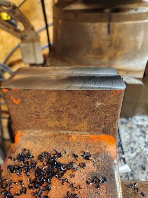
Then it was on to the mill. Rotated the turret, and setup an angle plate to mill a groove for the vise to nest into.

Not the most rigid of setups, but plunge roughing ruled here. For a primarily CNC boy these days this took what seemed like forever.....

Double check all my measurements before tearing down the setup, and then check the fit.


perfect. Then I reset the mill, and tossed it back on there to clean up the mount area I cut off.


Then just because I was in the mood, I flipped it over to clean up the saw cut that wandered. That blade is long overdue to be changed, but it keeps cutting so.....It doesn't really wander on tubing, but this fork was really bad. I half expected it to snap, but it kept chugging. The swage blocks I cut flat ways and there was no wander, but they took a while.....


Next I threw it all on the floor with a square for scale, so I can do some sketching tonight to connect the dots (la la la la).

Should be able to finish it off tomorrow, or a good chunk at least. The spring needs some forging to make it fit so I'm looking forward to that part.
This was the first time I've used that APKT 1" insert cutter, and it was awesome. I turned the shank down, and pressed on a collar to turn it into a Tormach TTS tool, but it also works great in a 3/4" collet on the Excello. I also have a 2" face mill that takes the same inserts, but I need to machine an arbor for it.
I just noticed how far that collet is hanging out the spindle nose while posting these pics. Seems excessive no? I'm going to investigate later. I have a lot of TTS tooling, so I can see me robbing them quite a bit to use like this. Less collet changes. Will also be handy when I build a power drawbar.

A couple months ago I picked up some forklift forks with the intention of making a striking anvil stand for a post vise I bought about 6-7 years ago. I also wanted to make some swage blocks and other forming aids, more to come on those later.
Last weekend I started cutting them up. While that was cutting, I cut up an old trailer leaf spring to replace the missing spring on the vise.
The swage blocks will be 12" long, so I zipped off three of them with the remaining length
I was rolling around some ideas all week on how to do this, and had some shop time this morning to do some milling. I first had to cut one of the mounts off. I tried cutting the welds with a angle grinder, but couldn't reach them all, so switched to the porta band and just zipped through the whole thing.
Then it was on to the mill. Rotated the turret, and setup an angle plate to mill a groove for the vise to nest into.
Not the most rigid of setups, but plunge roughing ruled here. For a primarily CNC boy these days this took what seemed like forever.....
Double check all my measurements before tearing down the setup, and then check the fit.
perfect. Then I reset the mill, and tossed it back on there to clean up the mount area I cut off.
Then just because I was in the mood, I flipped it over to clean up the saw cut that wandered. That blade is long overdue to be changed, but it keeps cutting so.....It doesn't really wander on tubing, but this fork was really bad. I half expected it to snap, but it kept chugging. The swage blocks I cut flat ways and there was no wander, but they took a while.....
Next I threw it all on the floor with a square for scale, so I can do some sketching tonight to connect the dots (la la la la).
Should be able to finish it off tomorrow, or a good chunk at least. The spring needs some forging to make it fit so I'm looking forward to that part.
This was the first time I've used that APKT 1" insert cutter, and it was awesome. I turned the shank down, and pressed on a collar to turn it into a Tormach TTS tool, but it also works great in a 3/4" collet on the Excello. I also have a 2" face mill that takes the same inserts, but I need to machine an arbor for it.
I just noticed how far that collet is hanging out the spindle nose while posting these pics. Seems excessive no? I'm going to investigate later. I have a lot of TTS tooling, so I can see me robbing them quite a bit to use like this. Less collet changes. Will also be handy when I build a power drawbar.

")

")