• Spring 2024 meetup in Calgary - date Saturday, April 20/2024. discussion Please RSVP Here to confirm and get your invitation and the location details. RSVP NOW so organizers can plan to get sufficient food etc. It's Tomorrow Saturday! you can still RSVP until I stop checking my phone tomorrow More info and agenda
  • We are having email/registration problems again. Diagnosis is underway. New users sorry if you are having trouble getting registered. We are exploring different options to get registered. Contact the forum via another member or on facebook if you're stuck. Update -> we think it is fixed. Let us know if not.
  • Spring meet up in Ontario, April 6/2024. NEW LOCATION See Post #31 Discussion AND THE NEW LOCATION

Old motorcycle projects

PeterT

Ultra Member
Premium Member
Cool!
- how are you liking your (I think you were one of the guys who bought Everlast) TIG welder so far?
- you mentioned jobbing out manifold for ceramic coating. Who does that kind of work & what kind of bucks if you don't mind me asking?
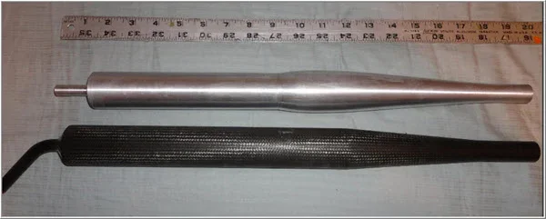
- the muffler can looks like steel? & you mention aluminum ends. If so, how do you attach dissimilar like that?
- are there internal baffles or noise screens or anything?
 

John Conroy

member
Premium Member
The Everlast TIG welder works great as far as I can tell with my limited skills. I need to spend more time practicing with it. It has a pulse feature that allows the current to be ramped up and down at variable frequency which makes it easier for rookies like me to weld thin metals without burn through. It will probably be a long time before I can make pretty welds with it. Somebody said a MIG welder is like a glue gun and I have lots of experience with MIG and can make decent looking welds with my Miller 180 even on thin metal without burn through. With this exhaust project I am trying to make the welds as invisible as possible so I'm using the MIG and then carefully buzzing them off with an 80 grit flap wheel on a 5" angle grinder then polishing the sander marks off with a Roloc disc on a 4" disc grinder.

I will probably get the ceramic coating done at Perfection Powder Coating in Edmonton and based on other stuff I've had done by them I suspect it will cost about $100-$150 for the whole system including the steel part of muffler can. I am going to machine 2 aluminum end caps that will be fastened with stainless button head cap screws. There will be 2 pipes into and 1 out of the end caps and the pipes will be held into the end caps with hidden grub screws and sealed with high temp RTV. The 3 pipes will be perforated inside the can and possibly wrapped in muffler packing. The design will be a lot like the muffler on my Buell. I'll document the muffler build so you can see how it works out. Of course if turns out to look like a monkeys butt no one will ever see it.:rolleyes:
 

John Conroy

member
Premium Member
More progress on the exhaust system part of this project. I've spent so much time on this muffler that I'm committed to using it even if it looks hideous. Kind of like having an ugly dog, it's ugly but it's mine. It started with a 1 foot length of 4" exhaust pipe from a diesel pick up with a cutout to fit around the right rear shock and keep it tighter to the bike. Then I made up 2 aluminum end caps and the 2 inlet pipes and 1 outlet with baffling holes drilled and an aluminum end piece for the outlet. I tack welded a support bracket to the frame to support the muffler and made a connecting brace from a piece of 3/16" aluminum sheet. My final judgment as to whether to keep it will be hearing how it sounds when I get the engine back together. I welcome your comments, here's some pics.

20161105_145631_zpsqqfieukr.jpg


20161105_145645_zpskncgod9z.jpg


20161105_175035_zpsax6cwpxh.jpg


20161110_134035_zps1l9kjp8k.jpg


20161111_141059_zpsl68b4z7d.jpg


20161111_143936_zps94kwibke.jpg


20161111_144824_zpsl3keqwoa.jpg


20161111_150527_zpsxixedmf6.jpg


20161112_153639_zpst323dbkq.jpg


20161112_153651_zpsgmmxi0so.jpg


20161112_153716_zpswgcwng9j.jpg


20161113_104101_zpsfyhkx7hb.jpg


20161113_104132_zpszjdgpfxh.jpg


20161113_104221_zps5zq47fyo.jpg


20161113_104229_zpsfi8qhzte.jpg
 

PeterT

Ultra Member
Premium Member
Very interesting John, looks great! I'm always curious about what's inside the magic cans, especially when they sound good with that mean gurgle. My background is RC models & I flew pattern (aerobatics) for many years. Before the rules changed favoring 4-srokes, 2-strokes were dominant & it was all about extracting max power but with hard stringencies. The biggest was noise limits, being reduced every 2 years from 98dB to 96.. I think its 94dB now. The pipes also had to take the heat & be as light as possible, I want to say they were about 75 grams. Unlike gasoline systems, cant use acoustic batting because of pre-mix oil mix in methanol (it would just mung up). Because we favoured long strokes for lower rpm & more torque, this pushed header/pipe assembly to long lengths like +60cm for the reflecting wave tuning. Longer length = increased weight. The aluminum pipes from Japan were a work of art, feather light, spun to maybe .030" WT. The baffle plates & cones & sub-pipes internals were spot/Tig welded through holes in the can & then polished over flush.

The only thing lighter was carbon fiber & I messed around with that. The plus was design freedom, you were not confined to circular pipe sections & carbon was relatively inexpensive. The minus was the resin was real expensive, nasty, toxic sh*t & you had to post-cure bake at 400F or so to make it stand up to exhaust temp. I had a few successful pipes. It was mostly R&D fun. I also had some failures. The best case scenario was a baffle that let go. If the rpms fell off & you heard this Bbbrrrt sound, the gig was up. The worst is when composite material eventually burns & degrades, this schmeg gets pumped back into the exhaust port with the reflective wave & basically destroys expensive engines very quickly. Ahhh the fun :) (fun is spelt $fun$)
 

Attachments

  • 2016-11-24_20-10-37.jpg
    2016-11-24_20-10-37.jpg
    29.7 KB · Views: 8

John Conroy

member
Premium Member
That's cool stuff Peter, I've never had any experience with RC model engines but I have built some 2 stoke expansion chambers in the past.
 

John Conroy

member
Premium Member
I made a little more progress on this mongrel bike. I bought a partial sheet of .040" aluminum to make an exhaust heat shield and some side covers with. First I mounted the muffler and inlet pipes in the mill and cut some slots so the clamps can tighten down onto the inner pipe.

20161125_121951_zpst4en4spi.jpg


Then I made up 2 brackets that bolt to the mounts I welded to the back side of the pipes earlier.

20161125_122519_zpsnhztktnt.jpg


20161125_122525_zpsvmkln453.jpg


20161125_122533_zpse7m32fi2.jpg


20161125_141242_zpsi76xi4ox.jpg


20161125_142755_zpsbhmvn9mm.jpg


Then I made a cardboard template to get the bolt hole spacing for the heat shield.

20161125_145106_zpsmdlldawb.jpg


I cut a piece of the aluminum sheet and screwed it by the 4 corners to a piece of 2" X 12" lumber and transferred the template holes onto the sheet metal.

20161125_151217_zpse1efgf4s.jpg


20161125_163939_zpsqdaqxtbm.jpg


I bent a small piece of sheet metal to work out how I was going to bend the heat shield.

20161125_160057_zpswqyniyox.jpg


I drilled the mounting holes and then a pattern of decorative holes then I lost my head a bit and experimented with some swirly pattern stuff using a Roloc disc.

20161125_180828_zpsons6mkbb.jpg


I took the piece to work and put into the metal brake to add some bends to fit around the pipes.

20161126_091830_zpsmoqtblai.jpg


I didn't take into account that the heat from using the Roloc Disc would work harden the aluminum and it cracked on the bends. A couple of off color words were uttered. Lesson learned.

20161126_091915_zpsm40ng0i6.jpg


I decided to take a break from the heat shield and work on the side covers. I'm going for a slimmer look than the bulbous stock covers give. I used some more of the sheet aluminum. I cut off the old seat latch and re-worked the stock side cover brackets with some heat and pliers then made up some backing nuts from short pieces of 1/4", threaded to 6mm. I spot welded the nuts to the back of the frame tabs.

20161127_104040_zpssxu6lzt0.jpg


20161127_105437_zps8ehl90at.jpg


20161127_100337_zpscfhnvntm.jpg


20161127_120122_zpsokqzq7v6.jpg


I also drilled out the spot welds on the lower side cover retainer brackets and welded nut into them as well.

20161127_123341_zpspi7dn9hy.jpg


20161127_124738_zpsyktkjld4.jpg
 

John Conroy

member
Premium Member
I installed the battery box and carbs to check clearances and made up some more cardboard templates. I originally made cut outs around the air filters but later decided to space the side panels out to provide air filter clearance.

You'll notice I painted my cracked heat shield to see how black would look. I kind of like it that way.

20161127_144747_zpsqxecfhjx.jpg


20161127_144757_zpsya9vtmtd.jpg


After the cardboard templates were made to fit I cut the aluminum sheet and made up some spacers to go behind 2 of the 3 bolts on each cover for correct fit.

20161203_192322_zpsoslm4do5.jpg


20161203_191826_zpsvwjeggas.jpg


I took the covers to work and put a small bend at the top of each on and also bent up my second attempt at a heat shield and bead blasted all 3 parts. No cracked sheet metal this time! All three parts will probably get painted.

20161204_082119_zpsjrgqkceh.jpg


20161204_082131_zps4nsifdep.jpg


20161204_082146_zpsggwrkqkj.jpg


20161204_082153_zpsssos1n2s.jpg


20161204_082600_zpskpsjnsy8.jpg
 

EricB

Active Member
Looks great, John! If you still wanted the engine turned look you could probably anneal the back-side of the aluminum before bending too.

This bike is going to be damn cool!

Sent from my B15 using Tapatalk
 

John Conroy

member
Premium Member
I spent almost the whole day Saturday making up some footpegs to replace the rubber covered originals. I used 2 strips of 1" by 1/4" hot rolled steel and milled notches spaced 1/2" on center, .180" deep, then milled that edge flat.

20161206_144543_zpssgyirrmj.jpg


20161206_150907_zps5imzlrud.jpg


I used the cheap Princess Auto metal bender to form the 180 degree bends with a 1" diameter die.

20161206_160006_zpslojagn9p.jpg


20161206_160442_zpszoa6qjws.jpg


I TIG welded the end caps on.

20161206_165458_zpsfzmygwwg.jpg


I machined some adapters to fit the Yamaha brackets and welded those to the end caps. The profile of the adapters allow the pegs to fold to 45 degrees. They are about 1/2" longer than the stock pegs.

20161209_174314_zpsildqalnp.jpg


20161210_114855_zpsekx0qo5q.jpg


20161210_114903_zpso32gd5rp.jpg


20161210_114913_zps349ltnfi.jpg


20161210_114924_zpsx9klgtzc.jpg


20161210_115013_zps5esalkom.jpg
 

John Conroy

member
Premium Member
I'm planning to use only the speedo from the XS but the one I have has 2 dents in the outer bezel. I used a simple plywood holding fixture and a curved tool to pry the crimp on the bezel open a little at a time until it was opened enough around the entire circumference to remove it. I also used a piece of sheet metal between the speedo and the prying tool to protect the plastic speedo body. I replaced the bezel with the undamaged one from the tach.

20161213_145726_zpsj3evwhic.jpg


20161213_151353_zpsnstr1kzc.jpg


20161213_151402_zpsfrwgrise.jpg


20161213_151502_zpsmvispbbh.jpg


20161213_152643_zpsatya9458.jpg


20161213_152648_zpsvrobsjkl.jpg


After the speedo was installed onto the undamaged bezel I used a length of brass rod to push the crimp closed again a little at a time until it is back to the original form. It is easier to repaint the bezel when it's on the gauge so I'll do that later.

20161213_154747_zpsbnji3wre.jpg


20161213_154758_zpslmos07zb.jpg
 

John Conroy

member
Premium Member
I used a chunk of 6061 to machine a speedo/handle bar mount. The Buell triple clamp has a weird diagonal bolt pattern for the handle bar hold down and I wanted to eliminate that as well as raise the bars up about 1.5". I milled the top of the original triple clamps bar mounts flat and parallel.

20161217_103413_zps6snmbdcm.jpg


I machined the adapter block to use 2 of the threaded holes on the triple clamp as simply hold downs and the other 2 as part of the bar mount hold downs thus giving me the perpendicular bar mounts I wanted and giving 4.25" spacing between the hold down clamps.
The Buell triple clamp used Imperial fasteners so all the holes are 5/16" NC.

20161217_113057_zpsb66u38yr.jpg


20161217_114032_zpswezx0dds.jpg


20161217_121003_zpswz6myedk.jpg


I machined the hold down clamps from 2 more small pieces of 6061 aluminum.

20161217_133137_zpsjoigxe45.jpg


20161217_133645_zps7lr6ttod.jpg


I drilled the hole for the handlebar to 3/4" the bore it to .875" for the 7/8" bars I will use. Both bar clamps are bored at once, stacked in the vise.

20161217_140815_zpseav5okpk.jpg


20161217_142505_zpsvggxzrk6.jpg


Then I drilled and countersunk the bolt holes and chamfered the edges.

20161217_172431_zpsydpibf4g.jpg


20161217_172841_zpsylecvpmx.jpg


I used a slitting saw to cut the clamps in half.

20161217_183346_zpsrsbx3h1h.jpg


20161217_185632_zpsjy3911ws.jpg


20161217_185818_zpstpspaimi.jpg


Using the same bolt hole spacing I drilled and tapped the extra mounting hole in the bracket for the hold down clamps.

20161217_192632_zpsxhc9s2e5.jpg


Now I have the starting point for my bar mount/speedo mount
 

John Conroy

member
Premium Member
I wanted to rubber mount the speedo as XS650's vibrate like paint shakers. I bent up a simple bracket from some 3/16" flat steel and milled the area that will fit on the aluminum bracket to fit between the mounting bolt holes. I found some sleeved rubber mounts left over from my DT250 build and measured the waist area of the rubber part. I did not have a drill bit the right size so I drilled the holes undersize then finished sizing with a boring bar.

20161218_104229_zpsilyg5pch.jpg


20161218_105443_zpsugcsdw1j.jpg


I drilled and tapped the 3 mounting holes in the aluminum bracket to 1/4" NC, the Buell triple clamps use Imperial fasteners.

20161218_111317_zpsk075xkm4.jpg


20161218_130926_zpskhq6io8m.jpg


20161218_114149_zpsgxyqmlhj.jpg


I soon realized that there was not enough room for the speedo bracket under the handlebar bracket, the rear bolt interfered with the steering stem bolt so I milled a pocket .200" deep in the aluminum bracket to move the speedo bracket upward to provide the necessary clearance. I drilled the 2 mounting holes for the speedo and milled a slot for cable clearance and fitted the handlebar.

20161218_130904_zps368k9v9g.jpg


20161218_131930_zpskwd5tfh8.jpg


20161218_132148_zpstmdoymbz.jpg


20161221_160442_zpsiffzvupd.jpg


20161221_160652_zpsmwblvbm6.jpg


20161221_161516_zpsc08ntovi.jpg


20161221_161841_zpsbj0kllwf.jpg


There's more to do on these brackets but the bar height feels right and I like the position of the speedo
 

PeterT

Ultra Member
Premium Member
Nice. If you ever find yourself having to replace unobtanium rubber mounts, seals etc. for your customs or historic bikes, I've done some dabbling with casting liquid urethane into machined molds. You can buy the 2-part goop in reasonable quantities & various durometer ratings through the arts/casting crowd - brands like Smooth-On & others. There are a few tricks to de-aerate & proper releasing agent, but not onerous & usually only problematic on larger volumes or stressed parts. Sorry no pics, but something to store in the noggin if the day comes
 

PeterT

Ultra Member
Premium Member
John when you slit slabs like this (in aluminum) do you take multiple passes to a certain DOC, or do you the whole depth & just walk in slowly? I've heard different schools of thought, maybe related to aluminum because is gummier? Another variation was a minor scoring slit just intended to guide the blade, but still cut full depth. I've always chickened out, taken multiple passes & it takes me forever. Despite decent arbors, my HSS blades inevitably make a scuff-scuff sound where all teeth are rarely engaged simultaneously.

I've thought about making a fence for the band saw table & sacrificial clamp plate out of MDF or something for less critical parts. On some things I just don't care what the finish is on the inside of the slit. I thought maybe mount up a 1-axis 'mill table accessory' or whatever they call those things. Then the part would be secure & you could feed it into blade? So many tools to make, so little time! :)
 

Attachments

  • 12-22-2016 0000.jpg
    12-22-2016 0000.jpg
    14.6 KB · Views: 6

John Conroy

member
Premium Member
I could only cut half way through each cap then I flipped them around in the vise to cut from the other side. I use a brush to apply oil to the blade before each pass and take a .125" depth cut each time in aluminum. With the cheap abor I use the blade is not quite on center but that's not a problem, in fact I think it helps clear the chips. I run the mill spindle quite slow, about 350 rpm. It cuts like a hot knife through butter. You have to ignore all the ugly noise it makes. It cuts very accurately. After each cap was cut in half I put them in the mill and removed
.010" from each side to smoothen the saw cut edge finish.
By the way climb cutting is not a good idea!
 
Last edited:

kylemp

Well-Known Member
No slitting saw is really concentric.. they all do that off center thing. As for the noise it's pretty painful eh?

Surprisingly you are supposed to do the cut in one pass, just adjust speeds and feeds to an appropriate level for the cut. Personally I run around 90 to 150rpm I believe and it goes pretty well.
 

John Conroy

member
Premium Member
I'm waiting for a couple of seals for the top end of the engine so I went to work on the tank and seat. I had previously moved the front tank mounts 1/2" back so I made up a new rear mount post for it. I just drilled the hole for it half and inch back from the original. The original was welded to the frame, this one is held onto the frame with a nut.

20161230_163300_zpscxasq7nl.jpg


20161230_163342_zpskzwdp26c.jpg


20161230_163521_zpsxp78d4kh.jpg


I found a vendor on eBay that sells reproduction seats for Yamaha enduro's and after some measuring I ordered one for a DT175. I thought about narrowing and shortening the original seat and getting a custom foam and cover made but that would have cost more than this seat did. I made up 6 mounting pads for the rubber cushions of the seat and fabricated a couple of hold down straps. I had to weld those 8 pieces to the frame so I chopped off the center stand mounts from the frame while I had it stripped down for the welding. The seat is thickly padded and nice and narrow and seems to be high quality and I like how it looks on the bike.

20161229_113036_zps5wotyxs2.jpg


20161231_163941_zpsqocfdv4f.jpg


20161231_163932_zpsogt19mbc.jpg


20161231_164000_zpsiyclwq6a.jpg


20161231_164200_zpsidnxf4pv.jpg


20170101_143930_zpskwllmq71.jpg


I finally got around to removing the brake caliper mount from the left fork leg to clean up the look of the fork.


20170101_111314_zps9xp6vzs0.jpg


20170101_113321_zpspvck5ewc.jpg


20170101_121816_zps53fnohar.jpg


20170101_121830_zpsodpfjjdk.jpg


20170101_124136_zpsv789kczg.jpg


20170101_124148_zpsapdcawgr.jpg


This is how is sits right now. After I get the engine together it will get a final mock-up assembly then be disassembled for paint. I haven't decided on a color yet.


20170101_143834_zps2vni8at2.jpg
 
Top